 EN
EN
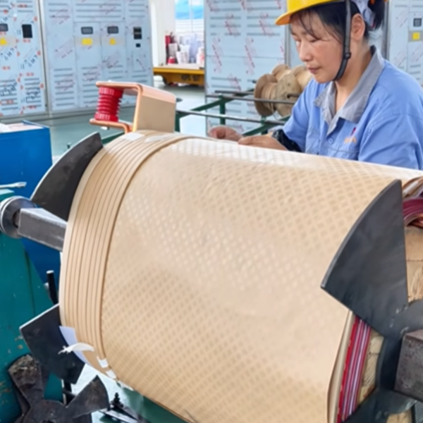
The transformer core stacking process directly affects no-load loss, excitation current, noise, mechanical stability, and long-term reliability. Among all manufacturing variables, the core joint design is especially important because every joint creates a small discontinuity in the magnetic path.
By selecting suitable core materials, adopting an optimized step-lap joint, and controlling lamination accuracy, manufacturers can reduce magnetic reluctance and localized flux distortion while improving overall transformer performance.

What Is Transformer Core Stacking?
Transformer core stacking is the process of assembling thin, insulated electrical steel laminations into a complete magnetic core. A typical production sequence includes:
- Material preparation and inspection
- Lamination cutting and notching
- Burr and dimensional inspection
- Step-by-step lamination stacking
- Joint alignment and clamping
- Core dimensional and insulation checks
- Final assembly with the windings
Each lamination must be positioned accurately. Poor alignment, excessive burrs, damaged insulation coatings, or uneven clamping may create unwanted air gaps, interlaminar currents, vibration, and additional losses.
Why Are Core Joints Important?
A transformer core cannot normally be manufactured as one continuous piece. Its limbs and yokes must be assembled from multiple laminations, creating joints in the magnetic circuit.
If these joints are poorly designed or assembled, the magnetic flux must cross larger or uneven gaps. This can increase local magnetic reluctance and cause flux crowding near the joint.
An optimized transformer core joint can help:
- Maintain a smoother magnetic flux path
- Reduce localized magnetic saturation
- Lower no-load loss and excitation current
- Control vibration and transformer noise
- Improve the mechanical stability of the core
- Support consistent long-term operation
The actual improvement depends on the transformer design, electrical steel grade, flux density, cutting accuracy, stacking quality, and clamping system.
Common Transformer Core Joint Designs
Butt-Lap Joint
In a butt-lap arrangement, lamination sections meet at relatively direct joints. The structure can be straightforward to manufacture, but joint gaps require careful control. Excessive or inconsistent gaps may increase magnetic reluctance and local flux distortion.
Mitred Joint
A mitred joint uses angled lamination ends, commonly around the corners where the limbs meet the yokes. This arrangement aligns the joint more closely with the direction of magnetic flux and can improve magnetic performance compared with a simple square joint.
Step-Lap Joint
A step-lap core distributes the joint across several lamination layers instead of concentrating it at one position. The laminations overlap in a controlled sequence, allowing the magnetic flux to transition more gradually through the joint area.
When properly designed and manufactured, a step-lap joint can:
- Reduce flux concentration at the corners
- Lower local saturation
- Improve no-load performance
- Reduce audible noise
- Create a more uniform magnetic circuit
Step-lap performance depends on precise step dimensions, consistent overlap, accurate stacking, and effective process control.
How Joint Optimization Improves Transformer Performance
1. Lower Magnetic Reluctance
Joint gaps interrupt the magnetic path. Controlling their size and distribution reduces the effective reluctance of the core and supports efficient magnetic flux transfer.
2. Reduced No-Load Loss
Core loss consists mainly of hysteresis loss and eddy-current loss. Joint geometry does not eliminate these losses, but better joint design can reduce localized flux distortion and excessive flux density that contribute to additional no-load loss.
3. Lower Excitation Current
A smoother magnetic path generally requires less magnetizing force. This can help control the current drawn by the transformer when the secondary winding is unloaded.
4. Better Noise Control
Magnetic flux concentration and uneven joints can contribute to vibration in the core. Accurate step-lap stacking and uniform clamping help limit movement between laminations and reduce one potential source of transformer noise.
5. Improved Mechanical Stability
A well-stacked and correctly clamped core must remain stable during transportation, installation, and operation. Consistent overlap and controlled compression help maintain the intended geometry without damaging the lamination insulation.
Key Strategies for Optimizing Core Stacking
Select the Right Electrical Steel
Transformer cores commonly use grain-oriented electrical steel with:
- Low specific core loss
- High magnetic permeability in the rolling direction
- Suitable saturation characteristics
- A consistent insulating surface coating
- Appropriate lamination thickness
Material selection should match the required voltage class, capacity, efficiency target, temperature-rise limit, and noise specification.
Control Cutting Accuracy and Burr Height
Cutting errors can change the intended joint geometry. Excessive burrs may damage the interlaminar insulation and create conductive paths between adjacent sheets, increasing the risk of localized heating and additional eddy-current loss.
Manufacturing controls should therefore include:
- Lamination length and angle inspection
- Step-dimension verification
- Burr-height monitoring
- Edge-condition inspection
- Identification and removal of damaged laminations
Use a Consistent Step-Lap Sequence
The stacking sequence must follow the engineering drawing. Incorrect layer order, inconsistent overlap, or misplaced laminations can shift the magnetic joint and create uneven air gaps.
Clear work instructions, layer identification, suitable positioning fixtures, and in-process inspections help maintain consistency.
Protect the Insulation Coating
The thin insulation coating on each lamination limits current flow between sheets. Scratches, contamination, metal particles, or excessive clamping pressure may compromise this insulation.
Core assembly areas should therefore be clean, dry, and free from loose metallic debris.
Apply Uniform Clamping Pressure
The core must be tight enough to maintain structural stability, but excessive pressure may distort laminations or damage their insulation coating. Clamping force should be applied uniformly and according to the approved transformer design and manufacturing procedure.
Quality Checks During Core Assembly
A reliable core-stacking process may include the following inspections:
- Electrical steel grade and thickness verification
- Lamination dimensions and cutting-angle checks
- Burr and edge-condition inspection
- Step-lap sequence confirmation
- Core window and overall dimension measurement
- Joint-gap and alignment inspection
- Core insulation checks
- Clamping and mechanical stability inspection
- No-load loss, excitation current, and noise testing on the completed transformer
Acceptance criteria should follow the approved design documents, customer specifications, and applicable standards.
Frequently Asked Questions
What is the main purpose of a step-lap transformer core?
A step-lap core spreads the joint across multiple lamination layers. This creates a more gradual magnetic transition and can reduce localized flux concentration, excitation current, no-load loss, and noise when correctly designed and assembled.
Does joint design affect transformer efficiency?
Yes. Core joints influence the magnetic path and can affect no-load loss. However, total transformer efficiency also depends on winding losses, conductor material, flux density, electrical steel quality, cooling design, and manufacturing accuracy.
Why are transformer cores laminated?
The core is divided into thin, insulated steel sheets to restrict circulating eddy currents. This helps reduce core loss and unwanted heating.
Why must lamination burrs be controlled?
Large burrs may penetrate or bridge the insulation between laminations. This can create conductive paths, increase localized eddy-current loss, and contribute to overheating.
Which joint design is best for a transformer core?
There is no universal solution for every transformer. Step-lap and mitred joints are widely used for their magnetic performance, but the optimal design depends on transformer capacity, core geometry, material, efficiency requirements, noise limits, and manufacturing capability.
Conclusion
Optimizing transformer core joints is not simply a matter of changing the lamination pattern. It requires coordinated control of material selection, cutting accuracy, stacking sequence, joint geometry, insulation protection, and clamping.
A precisely manufactured step-lap core can provide a smoother magnetic path, reduce localized flux distortion, support lower no-load losses, and improve mechanical stability. These benefits contribute to a transformer that is efficient, quiet, and reliable throughout its service life.
Looking for a Custom 35 kV Transformer?
Dingxin provides transformer manufacturing solutions tailored to project requirements, including rated capacity, voltage ratio, vector group, impedance, cooling method, efficiency target, enclosure, and installation environment.
Dingxin — 35 kV transformer manufacturer. Custom solutions are available.
Contact Dingxin to discuss your transformer specifications and request a customized technical proposal.
Table of Contents
- What Is Transformer Core Stacking?
- Why Are Core Joints Important?
- Common Transformer Core Joint Designs
- How Joint Optimization Improves Transformer Performance
- Key Strategies for Optimizing Core Stacking
- Quality Checks During Core Assembly
- Frequently Asked Questions
- Conclusion
- Looking for a Custom 35 kV Transformer?