Tel: +86-513-88779999
Email: [email protected]
Tel: +86-513-88779999
Email: [email protected]

Home > Products > Substations
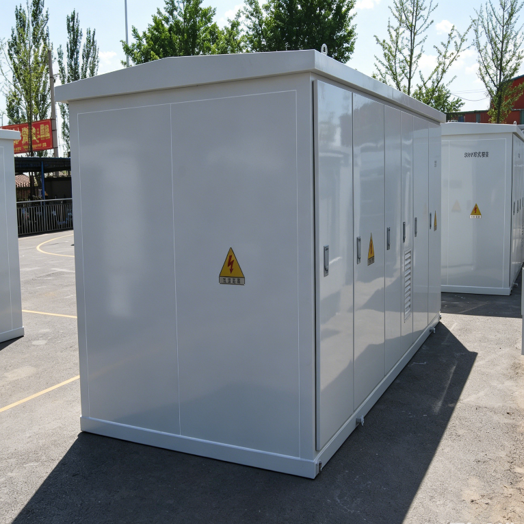
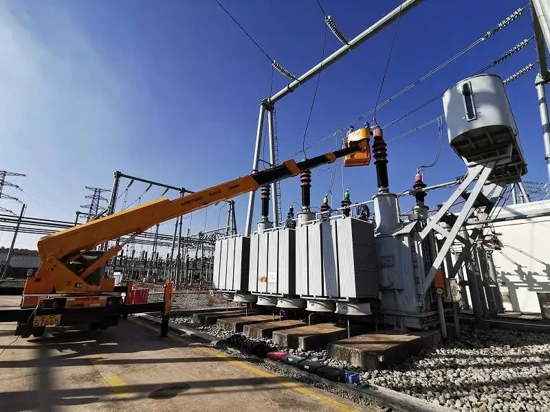

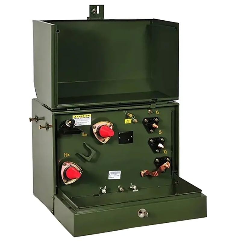
The DINGXIN Photovoltaic Combined Transformer is a purpose-built pad-mount transformer designed for solar PV inverter step-up and PV plant collector network applications. Covering a capacity range from 400 kVA to 10000 kVA, each unit integrates the transformer body, high-voltage switchgear, fuse, tap switch and auxiliary equipment into a single, factory-tested outdoor enclosure — serving as the central step-up node between the PV inverter array and the medium-voltage grid.
The transformer steps up the inverter output — typically 0.27 kV / 0.315 kV / 0.4 kV / 0.69 kV — to the collector-grid level of 10 kV / 35 kV / 38.5 kV, enabling direct interconnection with the PV plant's medium-voltage network. The stepped-up power is then transmitted to the plant substation via buried cable or overhead line.
As photovoltaic power generation becomes an increasingly important component of global energy production — driven by the worldwide push for clean, sustainable energy — DINGXIN PV combined transformers are engineered to meet the specific demands of modern solar plants:
Two structural configurations are offered:
Type |
Description |
Best For |
Fully Insulated Sub-Box Type |
Transformer and HV components in two independent boxes; enables separate maintenance and prevents oil cross-contamination |
Utility-scale PV plants requiring maximum uptime |
Porcelain Sleeve Outlet Box Type |
Traditional exposed-bushing outlet |
Retrofit or conventional PV substation integration |
For large PV installations, DINGXIN offers a split-cabin structure in which the high-voltage cabin, low-voltage cabin and transformer cabin form three independent units. The HV outgoing unit and LV incoming unit are physically separated from the transformer, providing enhanced safety and reliability. The cabin layout can be configured as mesh-type, linear (I-shaped), or L-shaped to suit the site footprint and collector-cable routing of any PV plant.
|
Parameter |
Specification |
|
Product Type |
Photovoltaic Combined Transformer |
|
Rated Capacity Range |
400–10000 kVA (up to 16000 kVA for large PV blocks on request) |
|
Rated Voltage Class |
≤ 35 kV and 10 kV (up to 38.5 kV) |
|
HV Ratings |
10 / 35 / 36.75 / 37 / 38.5 kV |
|
LV Ratings (Inverter Output) |
0.27 / 0.315 / 0.4 / 0.69 / 0.8 / 0.95 / 1.14 kV |
|
Frequency |
50 Hz (60 Hz optional) |
|
Transformer Insulation Class |
Class A |
|
Winding Temperature Rise |
≤ 65 K |
|
Oil-Top Temperature Rise |
≤ 60 K |
|
Connection |
Three-phase, double-winding |
|
Connection Group |
Dyn11 |
|
Voltage Regulation |
Off-circuit tap changing |
|
Insulation Level |
LI200AC85 / AC5 (for 35 kV class) |
|
Wiring Scheme |
Terminal (Z) / Ring Network (H) |
|
Structural Type |
Fully Insulated Sub-Box Type / Porcelain Sleeve Outlet Type / Split-Cabin Type |
|
Cabin Layout Options |
Mesh-type / Linear (I-shaped) / L-shaped |
|
12 kV Side Outlet |
Prefabricated cable joint + touchable plug-type arrester |
|
40.5 kV Side Outlet |
Prefabricated cable joint + touchable plug-type arrester |
|
12 kV Fuse Protection |
Plug fuse + backup protection fuse |
|
40.5 kV Fuse Protection |
Insert dry fuse |
|
HV-to-Transformer Connection |
Busbar connection (high operational safety) |
|
Radiator Design |
Fins directly exposed to ambient air for high cooling efficiency |
|
Protection — Oil Tank |
IP68 |
|
Protection — HV / LV Chamber |
IP45 |
|
Sealing Test |
50 kPa / 12 hours — no leakage |
|
Enclosure Treatment |
Anti-corrosion spray coating (seawater / salt-spray resistant), anti-theft design |
|
Automation |
High automation with agile communication; remote monitoring ready |
|
Parameter |
Specification |
|
Altitude |
≤ 3000 m |
|
Ambient Temperature |
−40 °C to +45 °C |
|
Outdoor Wind Speed |
≤ 30 m/s |
|
Relative Humidity (Daily Average) |
≤ 95% |
|
Relative Humidity (Monthly Average) |
≤ 90% |
|
Power Supply Waveform |
Approximately sine wave, three-phase approximately symmetrical |
|
Standard |
Scope |
|
IEEE C57.12.00 |
General Requirements for Liquid-Immersed Distribution, Power, and Regulating Transformers |
|
IEEE C57.12.10 |
Power Transformers > 500 kVA |
|
IEEE C57.12.34 |
Pad-Mounted, Self-Cooled, Three-Phase Distribution Transformers (HV side ≤ 34.5 kV) |
|
IEC 60076-1 |
Power Transformers — General |
|
IEC 60076-2 |
Power Transformers — Temperature Rise |
|
IEC 50588 |
Energy-Efficiency Standard for Distribution Transformers |
|
IEC 62271-202 |
High-Voltage / Low-Voltage Prefabricated Substations |
|
GB/T 6451 |
Specification and Test Codes for Three-Phase Oil-Immersed Power Transformers |
|
GB 20052 |
Energy Efficiency Limits and Energy Efficiency Grades for Power Transformers |
|
Rated Capacity (kVA) |
NX1 No-Load Loss (kW) |
NX1 Load Loss (kW) |
NX2 No-Load Loss (kW) |
NX2 Load Loss (kW) |
NX3 No-Load Loss (kW) |
NX3 Load Loss (kW) |
|
1000 |
0.63 |
10.35 |
0.75 |
10.35 |
0.86 |
10.93 |
|
1250 |
0.77 |
12.51 |
0.91 |
12.51 |
1.05 |
13.21 |
|
1600 |
0.93 |
14.94 |
1.10 |
14.94 |
1.27 |
15.77 |
|
2000 |
1.19 |
16.47 |
1.41 |
16.47 |
1.49 |
17.39 |
|
2250 |
1.29 |
17.06 |
1.52 |
17.06 |
1.68 |
17.55 |
|
2500 |
1.41 |
17.64 |
1.66 |
17.64 |
1.77 |
18.62 |
|
2750 |
1.52 |
19.05 |
1.80 |
19.05 |
1.98 |
20.11 |
|
3000 |
1.62 |
20.29 |
1.91 |
20.29 |
2.13 |
21.41 |
|
3150 |
1.67 |
20.70 |
1.98 |
20.70 |
2.21 |
21.85 |
|
3500 |
1.81 |
22.36 |
2.13 |
22.36 |
2.43 |
23.60 |
|
3750 |
1.93 |
23.60 |
2.25 |
23.60 |
2.58 |
24.91 |
|
4000 |
2.00 |
24.60 |
2.30 |
24.60 |
2.61 |
25.90 |
|
4250 |
2.11 |
26.08 |
2.49 |
26.08 |
2.88 |
27.53 |
|
4500 |
2.19 |
27.12 |
2.59 |
27.12 |
3.03 |
28.62 |
|
4750 |
2.29 |
27.66 |
2.71 |
27.66 |
3.10 |
29.16 |
|
5000 |
2.40 |
28.20 |
2.80 |
28.20 |
3.15 |
29.70 |
|
6300 |
2.90 |
31.50 |
3.40 |
31.50 |
3.78 |
33.30 |
|
8000 |
4.00 |
34.60 |
4.70 |
34.60 |
5.22 |
36.50 |
|
10000 |
4.80 |
40.80 |
5.70 |
40.80 |
6.30 |
43.00 |
|
12500 |
5.50 |
48.40 |
6.50 |
48.40 |
7.20 |
51.10 |
|
16000 |
6.70 |
59.20 |
7.90 |
59.20 |
8.73 |
62.50 |
NX1 is the highest energy-efficiency level (lowest loss), helping PV plant owners reduce auxiliary power consumption and carbon emissions over the 25+ year plant lifecycle.
Combined Transformer — G (Sharing Box) / F (Divided Box) — Three Phase — Performance Level Code — Terminal Type — Photovoltaic Power Generation — Rated Capacity (kVA) — Transformer Voltage Class (kV)
DINGXIN photovoltaic combined transformers are engineered to project-specific requirements. The following customization options are available:
|
Customization Area |
Options |
|
Rated Capacity |
Project-specific kVA rating matched to inverter / plant block size |
|
Primary / Secondary Voltage |
Custom HV / LV ratings within ≤ 35 kV class |
|
Wiring Scheme |
Terminal (Z) or Ring-Main (H) — or both in a single unit |
|
Structural Type |
Fully insulated sub-box type (dual-box) or porcelain sleeve outlet type |
|
Inverter Compatibility |
Winding design optimized for string, central or hybrid inverter output profiles |
|
Fuse Configuration |
Plug fuse + backup fuse (12 kV) or insert dry fuse (40.5 kV) |
|
Connection Group |
Dyn11, Yyn0 or other vector groups per project specification |
|
Tap Range |
±2×2.5% or ±5% (off-circuit or on-load tap changer) |
|
Oil Type |
Mineral oil or ester fluid (biodegradable, high flash point — preferred for environmentally sensitive sites) |
|
Enclosure Finish |
Anti-corrosion coating for desert, coastal or tropical PV environments |
|
Monitoring |
Optional oil temperature, winding temperature, online dissolved gas analysis (DGA) and SCADA integration |
|
Ambient Specials |
Anti-condensation heaters for humid/tropical sites; high-altitude derating; seismic qualification |
Contact DINGXIN with your PV project specification (inverter type, plant capacity, grid voltage, site conditions) for a tailored quotation.
Q1: What is a photovoltaic (PV) combined transformer? A PV combined transformer is a compact pad-mount unit designed for solar PV power plants. It steps up inverter output to the medium-voltage grid level and integrates the transformer body, HV switchgear, fuse and auxiliary equipment into a single outdoor enclosure, simplifying collector-line design for utility-scale and distributed PV projects.
Q2: How does a PV combined transformer differ from a standard distribution transformer? A PV combined transformer is purpose-built for solar plant topology: it handles the specific voltage and harmonic profile of inverter outputs, integrates HV switchgear and fuse protection in one enclosure for direct outdoor installation, and supports both terminal and ring-main collector-line wiring. Standard distribution transformers do not offer this level of integration or solar-specific engineering.
Q3: What structural types are available? (1) Fully insulated sub-box type — transformer and HV components in two independent boxes for separate maintenance. (2) Porcelain sleeve outlet box type for traditional installations. The fully insulated type is recommended for new utility-scale PV plants.
Q4: What protection level does the enclosure provide? The oil tank is rated IP68 and the HV/LV chambers are rated IP45. Each tank passes a 50 kPa / 12-hour sealing test to guarantee zero oil leakage under long-term outdoor UV, dust and humidity exposure.
Q5: Can the PV transformer handle inverter harmonics and DC injection? Yes. DINGXIN PV combined transformers are engineered to handle the harmonic-rich, potentially DC-biased current profile of PV inverter outputs. Winding design and insulation margin account for the specific thermal and dielectric stresses of solar inverter step-up duty.
Q6: What environmental conditions can the unit withstand? Altitude ≤ 3000 m, ambient temperature −40 °C to +45 °C, outdoor wind speed ≤ 30 m/s, daily-average humidity ≤ 95%, monthly-average ≤ 90%. The sealed enclosure withstands prolonged UV exposure, dust and thermal cycling typical of desert and tropical PV plant locations.
Q7: Which standards does the product comply with? IEEE C57.12.00, IEEE C57.12.10, IEEE C57.12.34, IEC 60076-1, IEC 60076-2, IEC 50588 and IEC 62271-202. Full type-test reports and FAT documentation are provided.
Q8: Can the PV transformer be customized for different inverter ratings and plant sizes? Yes. Rated capacity, primary/secondary voltages, terminal or ring-main wiring, connection group, tap range, oil type (mineral or ester), and monitoring options can all be customized to match inverter ratings from small commercial to utility-scale PV plants.

Jiangsu Dingxin Electric, a high-tech power equipment manufacturer, produces high-quality transformers and substations, serving global markets across 30+ countries.
Room 118, Building 8, 2999 Hutai Road, Baoshan District, Shanghai, China

Copyright © Jiangsu Dingxin Electric Co., Ltd. All Rights Reserved | Privacy Policy
 EN
EN