Tel: +86-513-88779999
Email: [email protected]
Tel: +86-513-88779999
Email: [email protected]
Transformers are essential components of solar power plants. They transfer electrical energy from photovoltaic (PV) generation systems to collection networks and grid connection points, helping ensure stable and efficient power transmission.
In a utility-scale solar project, oil-immersed transformers may operate continuously under changing loads, ambient temperatures, and environmental conditions. High temperatures, dust accumulation, humidity, insulation aging, oil leakage, and electrical connection problems can gradually affect transformer reliability.
Without a structured maintenance program, minor defects may develop into serious equipment failures, resulting in unplanned shutdowns, reduced power generation, and increased maintenance costs.
For solar power plant operators, transformer maintenance should include two complementary activities:
Online inspection: Routine condition checks while the transformer remains in service, without opening energized equipment or performing prohibited live work.
Outage maintenance: Inspection, testing, cleaning, and mechanical or electrical maintenance performed after the transformer has been properly isolated and made safe.
Combining these two approaches helps maintenance teams identify potential problems early and improve the long-term reliability of solar power infrastructure.
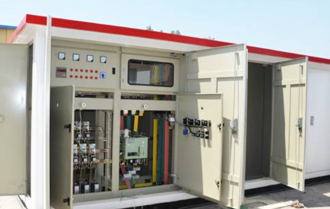
Routine online inspections allow operators to monitor transformer operating conditions and identify abnormal changes before they develop into equipment failures.
The following checklist covers the major inspection points for oil-immersed transformers in solar power plants.
Temperature is one of the most important indicators of transformer operating conditions.
During routine inspections, maintenance personnel should check:
The appearance and sealing condition of the oil temperature indicator.
The appearance and sealing condition of the winding temperature indicator.
Whether temperature readings are accurate and consistent with remote monitoring systems.
Whether the transformer tank surface temperature shows abnormal changes.
Whether winding temperature readings remain within the manufacturer's specified operating limits.
Whether temperature changes correspond reasonably with transformer load and ambient temperature.
Infrared thermography can also help identify abnormal heating at external electrical connections, terminals, and other accessible components.
A sudden temperature increase or an unusual difference between comparable connection points may indicate loose connections, excessive contact resistance, cooling problems, or abnormal loading.
Transformer oil provides both electrical insulation and heat dissipation. Maintaining an appropriate oil level is therefore essential.
Inspect the following:
Check whether the oil level gauge is intact, properly sealed, and functioning correctly.
Compare the indicated oil level with the manufacturer's oil level-versus-temperature reference curve.
Check for condensation or moisture inside the oil level gauge.
Observe whether the oil level changes abnormally over time.
Investigate any unexplained reduction in oil level.
Oil level should always be evaluated in relation to oil temperature. A lower reading under cold conditions does not necessarily indicate oil leakage.
Oil leakage can reduce insulation reliability and may indicate deterioration of seals, gaskets, or mechanical connections.
Inspect potential leakage points, including:
Flanges and valves
Temperature and oil level indicators
Tap changer connections
Cooling radiators and cooling equipment
Transformer tank joints
Oil pipes and connecting components
Welded joints and sealing surfaces
All connections should remain properly sealed, with no visible oil leakage or abnormal oil stains.
Any leakage should be investigated and repaired according to the manufacturer's maintenance instructions.
A transformer normally produces electromagnetic humming and some mechanical vibration during operation.
Maintenance personnel should monitor changes in sound and vibration rather than simply checking whether noise is present.
Important inspection points include:
Whether operating noise has changed noticeably compared with normal conditions.
Whether external connections or structural components are loose.
Whether cooling fans or oil pumps produce abnormal noise.
Whether unusual discharge, arcing, or flashover sounds are present.
Whether vibration levels show abnormal changes.
Unusual noise may indicate loose components, cooling equipment faults, abnormal electromagnetic conditions, or other developing defects.
A reliable grounding system is essential for electrical safety and transformer protection.
Inspect:
Transformer tank grounding connections.
Neutral grounding connections.
Core and core-clamp grounding arrangements.
Grounding conductors and connection points.
Signs of corrosion, overheating, or mechanical damage.
Grounding current should be monitored according to the equipment design and applicable operating standards.
Abnormal neutral or core grounding current requires further investigation. Any numerical acceptance limit should be based on the transformer manufacturer's specifications and the applicable electrical regulations.
The mechanical foundation and external electrical connections directly affect transformer operating stability.
Check the following:
No abnormal settlement, cracking, or structural damage to the transformer foundation.
No visible deformation or displacement of the transformer installation.
No abnormal heating at cable, busbar, and terminal connections.
No loose or corroded electrical connection points.
No visible signs of overheating or discoloration.
No abnormal discharge or electrical tracking.
Infrared inspection is particularly useful for identifying temperature differences at electrical connection points before they develop into more serious problems.
The cooling system plays a critical role in maintaining safe transformer operating temperatures.
For oil-immersed transformers equipped with forced-air cooling, inspect:
Cooling fans
Fans operate normally without abnormal noise or vibration.
No reverse rotation, jamming, or unexpected shutdown.
Fan motors and electrical connections remain in good condition.
Oil circulation and flow indicators
Oil flow indicators show the correct operating condition.
No abnormal pointer fluctuation.
Oil pumps operate as designed, where applicable.
Radiators and cooling pipelines
No oil leakage at radiators, valves, or connecting pipes.
Radiator surfaces are clean and free from excessive dust accumulation.
Airflow is unobstructed.
Comparable radiator sections show reasonably consistent temperature distribution under similar operating conditions.
Automatic cooling control
Cooling fans and pumps start and stop according to the configured temperature and load control logic.
Automatic and manual control functions operate correctly.
Cooling equipment status is consistent with the operating requirements.
Dust accumulation and restricted airflow should be addressed promptly because they can reduce heat dissipation efficiency.
Bushings provide electrical insulation and allow conductors to pass safely through the transformer tank.
During online inspection, check:
External condition
Porcelain surfaces have no cracks, chips, or serious contamination.
No visible discharge marks or abnormal surface tracking.
Silicone rubber sheds have no cracking, detachment, or damaged bonding areas.
External insulation surfaces remain clean and intact.
Oil leakage
No leakage around bushing flanges or sealing connections.
Capacitive bushings show no abnormal leakage around the terminal and sealing structures.
Temperature condition
Use infrared thermography to inspect accessible bushing terminals and external connections.
Check for abnormal heating at terminal connections.
Monitor accessible test taps and associated terminal boxes for abnormal temperature conditions.
Any suspected internal bushing defect should be evaluated using appropriate diagnostic testing rather than relying only on visual inspection.
The breather helps reduce moisture entering the transformer conservator during changes in oil volume.
Maintenance personnel should inspect:
Whether the silica gel desiccant shows signs of moisture absorption.
Whether the breather housing is intact and free from cracks.
Whether the oil seal cup contains an appropriate oil level.
Whether the breather passage is unobstructed.
Whether normal breathing activity can be observed as transformer oil temperature changes.
For color-indicating silica gel, replacement should follow the desiccant manufacturer's instructions. If approximately two-thirds or more of the silica gel has changed color, replacement may be required, depending on the specified desiccant type.
If a conservator is installed, also inspect its oil level, oil appearance, breather, and sealing condition.
An on-load tap changer (OLTC) regulates transformer voltage by changing winding connections while the transformer remains energized under permitted operating conditions.
Routine inspection should include:
The external condition of the operating mechanism.
The condition of shafts, pins, locking components, and transmission parts.
Whether the gearbox shows signs of oil leakage.
Whether the tap position indicator is correct.
Whether local and remote tap position indications are consistent.
Whether the control cabinet and operating mechanism show abnormal conditions.
If corrosion, abnormal vibration, or mechanical defects are identified, the cause should be investigated and appropriate maintenance scheduled.
Internal OLTC inspection and mechanical servicing must follow the manufacturer's procedures and applicable safety requirements.
Control cabinets and secondary terminal boxes support transformer monitoring, protection, and cooling control.
Check:
Cabinet sealing and protection against water and moisture.
Space heater operation, where installed.
Cable entry sealing and protection against small animals.
Terminal connections for looseness, corrosion, or overheating.
Whether internal components show signs of electrical discharge.
Whether indicators, fuses, and switches operate correctly.
Whether grounding connections are intact.
Whether cooling control switches and operating modes are correctly configured.
Infrared thermography can help detect abnormal heating at accessible electrical terminals.
Dissolved gas analysis is an important diagnostic method for evaluating the internal condition of oil-filled power transformers.
It detects gases dissolved in transformer oil that may be generated by electrical or thermal faults.
Maintenance teams should pay attention to:
Changes in total dissolved combustible gases.
Abnormal increases in individual gas concentrations.
Acetylene (C₂H₂), which may be associated with high-energy electrical discharge.
Hydrogen (H₂), which may indicate certain electrical or insulation-related faults.
Methane (CH₄), ethylene (C₂H₄), and ethane (C₂H₆), which can provide information about thermal fault conditions.
Carbon monoxide (CO) and carbon dioxide (CO₂), which may be associated with paper insulation degradation.
The trend of gas concentration is often as important as an individual measurement.
Results should be interpreted using appropriate standards, such as IEC 60599, together with transformer operating history and other diagnostic information.
A sudden increase in acetylene or total combustible gases requires prompt technical assessment.
Solar power plants may experience temporary grid outages, planned maintenance shutdowns, or equipment isolation periods.
These periods provide opportunities to perform maintenance tasks that cannot be completed during normal transformer operation.
However, an external grid outage does not automatically mean that a transformer is safe to work on. Before maintenance begins, the equipment must be properly isolated from all possible sources of electrical energy, secured against accidental re-energization, and verified de-energized in accordance with site safety procedures.
The following maintenance items are particularly important.
During an outage, maintenance personnel can perform more detailed cooling system inspections.
Recommended tasks include:
Clean radiator surfaces and cooling air passages.
Inspect cooling pipes, brackets, and support structures for dirt and corrosion.
Check cooling equipment for mechanical damage.
Inspect valves and confirm that their positions are correct.
Check all cooling system connections for oil leakage.
Apply appropriate anti-corrosion treatment where required.
Electrical insulation resistance testing of cooling equipment components should be performed using the voltage specified by the manufacturer and applicable procedures.
A commonly used field reference is a minimum insulation resistance of 1 MΩ where applicable, but the actual acceptance criteria must be determined from the equipment documentation and relevant standards.
Capacitive bushings require careful inspection because internal insulation deterioration can lead to serious electrical failures.
During an outage, check:
Porcelain housing
No cracks, chips, or surface damage.
No serious contamination or visible discharge marks.
No significant flange corrosion.
Sealing and oil level
The bushing-to-transformer tank sealing connection is intact.
Oil level is within the specified range, where applicable.
No visible leakage.
Electrical connections
Terminal connections are mechanically secure.
No oxidation or overheating marks.
Contact surfaces are in good condition.
Test tap and grounding
The bushing test tap is properly sealed.
No signs of overheating or discharge.
The grounding connection is secure and correctly installed.
Where required, perform capacitance and dielectric dissipation factor (tan delta) testing according to the bushing manufacturer's recommendations.
For conventional porcelain bushings, outage maintenance should include:
Inspecting the porcelain surface for cracks, damage, and contamination.
Checking flanges for corrosion.
Inspecting sealing components for oil leakage.
Checking electrical terminals for looseness and oxidation.
Confirming the integrity of the external insulation structure.
Evaluating creepage distance requirements according to the site's pollution level and insulation coordination design.
Damaged bushings should not be returned to service without appropriate technical evaluation.
An off-circuit tap changer must only be operated after the transformer has been properly de-energized and made safe.
Inspection items include:
Checking mechanical travel limits and operating positions.
Confirming smooth operation without jamming.
Inspecting sealing components for oil leakage.
Checking fasteners and mechanical connections.
Confirming that the indicated tap position matches the actual position.
Inspecting contacts and internal components according to the manufacturer's instructions.
Correct operation and position indication are essential for maintaining the designed transformer voltage ratio.
Although an OLTC is designed for voltage regulation during operation, its internal inspection and servicing generally require appropriate isolation and maintenance procedures.
Recommended inspection tasks include:
Operating mechanism
Check the mechanical transmission system.
Inspect gears, shafts, and lubrication conditions.
Confirm correct position indication.
Inspect electrical connections and control wiring.
Check limit switches and interlocking devices.
Verify manual and motor-driven operating functions according to the manufacturer's maintenance procedure.
Inspect relay contacts for corrosion or damage.
Operational checks
Where specified by the manufacturer, perform a complete operating sequence to verify mechanical movement and switching control.
Electrical insulation testing
Measure the insulation resistance of applicable electrical components using the specified test voltage.
The commonly referenced 1 MΩ threshold should not be treated as a universal acceptance value. The applicable manufacturer's limits and testing standards take precedence.
The Buchholz relay is a protective device installed in the oil pipeline between the transformer tank and conservator on applicable transformer designs.
It can detect gas accumulation and abnormal oil flow associated with certain internal faults.
During maintenance, check:
Relay housing and connections for oil leakage.
Inspection window cleanliness and readability.
Gas accumulation and alarm indications.
Mechanical operation of alarm and trip contacts.
Correct operation of the associated protection circuits.
Protection circuit testing should be carried out using approved procedures without compromising transformer protection.
A pressure relief device protects the transformer tank against excessive internal pressure.
Inspect:
The device housing and sealing surfaces.
Signs of oil leakage or oil discharge.
Mechanical condition of the operating indicator.
Whether the indicator moves freely.
Correct operation of the associated alarm or trip circuit.
Any evidence of previous pressure relief operation should be investigated before the transformer is returned to service.
The winding temperature indicator provides important information about transformer thermal conditions.
During an outage, check:
Whether moisture or condensation is present inside the indicator.
Whether the temperature indication is consistent with the expected condition.
Whether alarm and trip contact settings are correct.
Whether the associated secondary circuits operate properly.
The temperature simulation and contact verification procedures should follow the manufacturer's instructions.
Inspect the oil level gauge for:
Internal condensation or moisture.
Damaged glass or housing.
Abnormal oil level indications.
Incorrect mechanical operation.
Proper operation of any associated alarm contacts.
Compare the indication with actual operating conditions and the manufacturer's oil level-temperature reference.
For transformers equipped with forced oil circulation, inspect the oil flow indicator.
Check:
Whether the indicator is free from condensation.
Whether the pointer is in the correct position.
Whether the indication is stable during pump operation.
Whether oil flow reaches the expected operating range.
Whether the associated alarm contacts function correctly.
Abnormal pointer movement may indicate an oil circulation problem and should be investigated.
Secondary circuits connect transformer monitoring devices, protective relays, alarms, and control equipment.
During an outage, inspect:
Wiring insulation condition.
Terminal tightness and corrosion.
Cable connections inside terminal boxes.
Water and dust protection of control cabinets.
Relay and alarm circuit integrity.
Correct operation of cooling and protection control functions.
Insulation resistance testing may be performed on suitable isolated secondary circuits using the specified test voltage.
Sensitive electronic devices and components must be disconnected or protected as required by the manufacturer's testing instructions.
To improve maintenance efficiency, solar power plant operators can organize transformer maintenance into a structured inspection program.
| Maintenance Item | Online Inspection | Outage Maintenance |
|---|---|---|
| Oil and winding temperature | Monitor readings and trends | Verify instruments and alarm contacts |
| Oil level | Check gauge and temperature compensation | Inspect gauge and associated contacts |
| Oil leakage | Inspect accessible connections | Inspect seals, flanges, and valves |
| Cooling system | Monitor fans, pumps, and oil flow | Clean radiators and inspect components |
| Transformer bushings | Check external condition and temperature | Perform detailed inspection and diagnostic tests |
| Breather | Check silica gel and oil seal | Clean and replace desiccant as required |
| Tap changer | Monitor position and operation | Inspect mechanism and perform specified tests |
| Buchholz relay | Monitor alarm indications | Verify mechanical and protection circuit functions |
| Pressure relief device | Monitor status and leakage | Inspect mechanical condition and trip circuit |
| Grounding system | Check visible connections and abnormal current | Inspect connections and perform specified tests |
| Control cabinets | Check indicators and cabinet condition | Inspect wiring, terminals, and insulation |
| Transformer oil | Monitor DGA trends and oil condition | Collect samples and perform additional oil tests |
The actual maintenance frequency should be determined by the transformer manufacturer's recommendations, operating conditions, local regulations, and the site's maintenance strategy.
Effective transformer maintenance requires more than completing a checklist. It requires a systematic approach to condition monitoring, defect management, and maintenance planning.
Instead of relying exclusively on fixed maintenance intervals, operators should combine routine inspections with condition-monitoring data.
Useful monitoring parameters include:
Oil temperature.
Winding temperature.
Transformer load.
Oil level.
Cooling system status.
Dissolved gas concentrations.
Insulation diagnostic results.
Infrared temperature measurements.
Historical data makes it easier to identify abnormal trends and schedule maintenance before a defect develops into a major failure.
Unplanned grid outages can create opportunities for additional maintenance, but only when the site safety conditions and isolation arrangements allow it.
Maintenance teams should prepare inspection tools, test equipment, spare parts, and work procedures in advance.
A prioritized maintenance plan helps ensure that critical tasks are completed within the available outage window.
Each transformer should have a maintenance history that includes:
Routine inspection records.
Oil test and DGA reports.
Temperature and load trends.
Infrared inspection records.
Defect and repair reports.
Tap changer operation records.
Cooling system maintenance history.
Electrical test results.
These records support condition assessment, maintenance planning, and long-term equipment lifecycle management.
Different transformer designs may use different cooling configurations, insulation systems, bushings, protection devices, and tap changer mechanisms.
Therefore, maintenance procedures and acceptance criteria should always be checked against the specific transformer drawings, technical specifications, and manufacturer's operation and maintenance manual.
Working with an experienced transformer manufacturer can help operators clarify technical requirements and select appropriate replacement components.
Jiangsu Dingxin Electric Co., Ltd. specializes in the manufacturing of power transformers and related electrical equipment for utility, industrial, and renewable energy applications.
With more than 30 years of industry experience and an annual transformer production capacity exceeding 50 million kVA, Dingxin Electric provides transformer solutions for customers in international power markets.
Its product portfolio includes:
Oil-Immersed Transformers
Cast Resin Dry-Type Transformers
Pad-Mounted Transformers
Pole-Mounted Transformers
Prefabricated Substations
Solar Power Transformer Solutions
Low-Voltage Switchgear
For solar power plant projects, transformer selection should consider rated capacity, voltage ratio, impedance, vector group, cooling method, insulation level, environmental conditions, and grid connection requirements.
Dingxin Electric supports customized transformer solutions based on project specifications and application requirements.
Whether the project involves utility-scale solar generation, industrial power distribution, or renewable energy grid integration, selecting a suitable transformer and establishing a sound maintenance strategy are both essential for long-term operating reliability.
Visit the official website to explore Dingxin transformer products and manufacturing capabilities:
Website: https://www.dingxinelectric.com/
Contact Dingxin Electric to discuss customized transformer requirements for your next power distribution or renewable energy project.
Routine visual and operational inspections should follow the site's operating procedures and the transformer manufacturer's recommendations. Temperature, oil level, cooling system status, leakage, and abnormal noise are important inspection points. More detailed diagnostic testing should be scheduled according to operating conditions and equipment history.
Common warning signs include abnormal temperature increases, falling oil levels, oil leakage, unusual noise or vibration, cooling system failures, abnormal dissolved gas trends, and overheating at electrical connections.
These symptoms should be investigated promptly to determine their cause.
DGA helps identify gases generated by internal thermal and electrical faults. Monitoring gas concentrations and trends can provide early indications of insulation deterioration, overheating, and electrical discharge.
Important items include cooling equipment, bushings, tap changers, Buchholz relays, pressure relief devices, temperature indicators, oil level gauges, oil flow indicators, grounding connections, and secondary control circuits.
The exact scope depends on the transformer design, outage duration, and maintenance requirements.
Some external visual inspections, remote monitoring activities, and approved non-intrusive diagnostic methods can be performed while the transformer remains in service.
However, internal inspection, mechanical servicing, electrical isolation testing, and other intrusive maintenance tasks require the equipment to be properly isolated and made safe. Personnel must follow site safety procedures and applicable electrical regulations.
IEC 60076 provides the general framework for power transformer requirements and testing. IEC 60599 provides guidance on interpreting dissolved gases in mineral oil and other insulating liquids. Other applicable standards and manufacturer-specific procedures may also be required depending on the equipment and jurisdiction.
Reliable oil-immersed transformer operation is essential for maintaining stable power generation and grid integration in solar power plants.
A comprehensive maintenance strategy should combine routine online inspections, planned outage maintenance, oil condition analysis, electrical testing, and long-term condition monitoring.
By identifying abnormal operating conditions early and following manufacturer-recommended maintenance procedures, solar power plant operators can reduce equipment risks, improve transformer availability, and support the long-term performance of renewable energy infrastructure.
Dingxin Electric provides customized oil-immersed and dry-type transformer solutions for power distribution and renewable energy projects worldwide.

Jiangsu Dingxin Electric, a high-tech power equipment manufacturer, produces high-quality transformers and substations, serving global markets across 30+ countries.
Room 118, Building 8, 2999 Hutai Road, Baoshan District, Shanghai, China


Copyright © Jiangsu Dingxin Electric Co., Ltd. All Rights Reserved | Privacy Policy
 EN
