
 EN
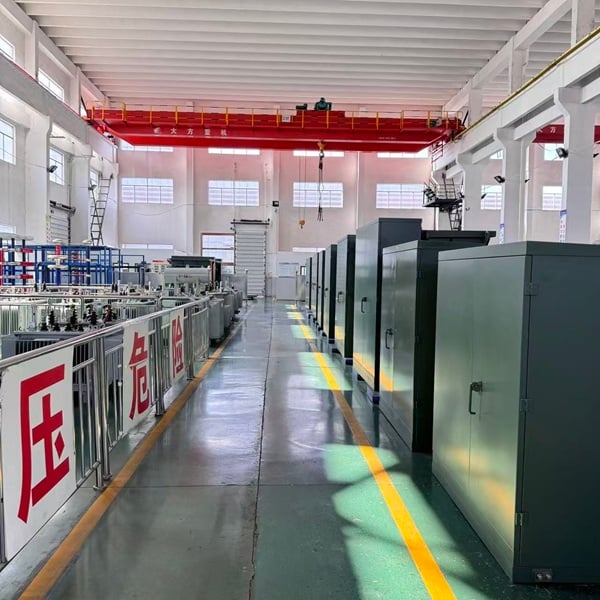
The growing integration of photovoltaic (PV) generation and battery energy storage systems (BESS) is transforming how renewable energy plants connect to electrical distribution networks.
Unlike conventional solar installations that primarily export generated electricity, hybrid PV-BESS facilities can operate in multiple modes: exporting solar energy, charging batteries from the grid or solar generation, discharging stored energy, and providing grid support services.
These changing operating conditions introduce new engineering requirements for the photovoltaic step-up substation and its associated transformers.
A properly engineered bidirectional power flow transformer must accommodate varying load profiles, maintain acceptable thermal performance, withstand specified electrical disturbances, and operate within a coordinated protection system.
For solar EPC contractors, BESS integrators, utility engineers, and industrial power system designers, transformer selection is therefore a critical part of project reliability and lifecycle cost management.
This guide examines the electrical, thermal, and protection challenges of PV and BESS integration and explains how to specify a suitable step-up transformer for modern hybrid renewable energy projects.
1. Understanding PV-BESS Hybrid Power Systems
1.1 How Solar-Plus-Storage Changes Power Distribution
In a conventional grid-connected photovoltaic plant, solar inverters convert DC electricity from photovoltaic modules into AC electricity.
A step-up transformer increases the inverter output voltage to the required medium-voltage distribution level, such as 10 kV, 20 kV, or 35 kV.
Power normally flows from the solar generation equipment toward the collection network or utility grid, although auxiliary loads and some operating conditions may result in limited reverse flow.
When battery energy storage is introduced, the electrical architecture becomes more complex.
A hybrid PV-BESS installation may operate in several modes:
| Operating Mode | Energy Flow | Transformer Consideration |
|---|---|---|
| Solar generation | PV inverter → Transformer → Grid | Continuous generation loading |
| Battery charging from grid | Grid → Transformer → BESS PCS | Reverse active power flow |
| Battery discharging | BESS PCS → Transformer → Grid | Export loading and thermal performance |
| Solar and BESS export | PV + BESS → Transformer → Grid | Combined maximum output |
| Grid support | Bidirectional active/reactive power exchange | Voltage regulation and protection coordination |
| Standby | Minimal active power transfer | No-load losses and auxiliary demand |
In AC-coupled systems, photovoltaic inverters and battery power conversion systems (PCS) may connect to a common AC collection network.
A dedicated BESS transformer, a shared step-up transformer, or multiple transformer configurations may be used depending on system capacity and electrical architecture.
1.2 Why Bidirectional Power Flow Matters
A conventional transformer is generally capable of transferring AC power in either direction, provided that its voltage, current, insulation, thermal, and protection limits are respected.
Therefore, bidirectional power flow does not inherently require a completely different transformer magnetic design.
The engineering challenge arises from the operating conditions associated with hybrid solar and storage systems.
These may include:
-
Repeated changes between charging and discharging.
-
Variable loading throughout the day.
-
Inverter-generated harmonic currents.
-
Reactive power exchange.
-
Potential DC current injection.
-
Different fault-current contributions in various operating modes.
-
Voltage changes across the collection network.
-
Long periods of energized standby operation.
A photovoltaic step-up transformer must be evaluated against these actual operating conditions rather than power-flow direction alone.
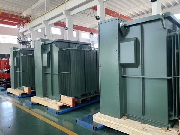
2. Thermal Stress and Loading Challenges in BESS Step-Up Transformers
2.1 Thermal Cycling During Charging and Discharging
Thermal performance is a major consideration when selecting a BESS step-up transformer.
The temperature of transformer windings and insulating liquid depends primarily on electrical losses, cooling conditions, ambient temperature, and previous loading history.
A battery storage plant may experience several charging and discharging periods within a single day.
For example, a battery system may charge during high solar generation, discharge during the evening peak, and provide additional grid services during intermediate periods.
Although reversing power flow does not itself cause additional heating at the same RMS current, frequent changes in current magnitude can produce repeated heating and cooling cycles.
These cycles can influence:
-
Winding hot-spot temperature.
-
Insulation aging rate.
-
Thermal expansion and contraction.
-
Mechanical loading of winding support structures.
-
Long-term oil and insulation condition.
The resulting temperature variation depends on load duration and the thermal time constants of the transformer.
Consequently, transformer sizing should account for the complete operating profile rather than only the nominal PCS power rating.
2.2 Evaluating Transformer Hot-Spot Temperature
Transformer insulation life is strongly influenced by winding hot-spot temperature.
For oil-immersed transformers, the approximate hot-spot temperature can be represented as:
θH = θA + ΔθTO + ΔθH
Where:
-
θH: Winding hot-spot temperature.
-
θA: Ambient temperature.
-
ΔθTO: Top-oil temperature rise above ambient.
-
ΔθH: Winding hot-spot gradient above top-oil temperature.
Actual temperature rise varies with load, cooling design, transformer geometry, and operating history.
Engineers should evaluate loading using applicable guidance such as IEEE C57.91 or IEC 60076-7, depending on the project specification.
For BESS installations, a representative time-series load profile can help identify thermal risks that may not appear in a simple nameplate capacity calculation.
2.3 DC Current Injection and Core Saturation
Power electronic converters may introduce small DC components into their AC output under certain conditions.
Excessive DC current injection can create magnetic bias in a transformer core, potentially resulting in:
-
Increased magnetizing current.
-
Core saturation.
-
Additional stray losses.
-
Localized heating.
-
Increased acoustic noise.
-
Abnormal vibration.
However, well-designed grid-connected inverters and PCS equipment incorporate control and protection functions intended to limit DC injection.
DC offset should be assessed as a power-quality and equipment compatibility requirement, not assumed to be an unavoidable consequence of bidirectional operation.
Transformer manufacturers should request the PCS manufacturer's specified DC injection limits when assessing compatibility.
3. Harmonic Distortion and Transformer Losses in Hybrid PV-BESS Systems
3.1 Why Power Electronic Converters Matter
Photovoltaic inverters and battery PCS equipment use semiconductor switching and control algorithms to convert electrical energy.
These conversion processes may introduce harmonic current components.
Depending on converter topology, switching frequency, control strategy, and filtering, relevant harmonic components can include the 5th, 7th, 11th, and 13th harmonics, as well as higher-frequency components.
The actual harmonic spectrum must be obtained from the equipment manufacturer or a suitable power-quality study.
Harmonic currents may increase:
-
Winding eddy-current losses.
-
Stray losses in structural components.
-
Additional conductor heating.
-
Overall transformer thermal loading.
-
Potential resonance-related electrical stress in the wider system.
Because harmonic-related eddy-current losses are frequency-dependent, evaluating only fundamental-frequency RMS current may underestimate certain loss contributions.
3.2 Do BESS Transformers Require K-Factor Ratings?
K-factor is commonly used to describe a transformer's capability to accommodate specified nonlinear load characteristics, particularly in certain dry-type transformer applications.
However, selecting an arbitrary K-4, K-9, or K-13 rating is not a universal requirement for liquid-immersed solar and energy storage step-up transformers.
For medium-voltage liquid-filled transformers, a more appropriate engineering approach is to evaluate the expected harmonic spectrum and resulting additional losses.
IEEE C57.110 provides methods relevant to assessing transformer capability under nonsinusoidal load-current conditions within its defined scope.
Recommended engineering steps include:
-
Obtain the PV inverter and BESS PCS harmonic current data.
-
Evaluate expected operating conditions in both charging and discharging modes.
-
Calculate additional winding and stray losses where applicable.
-
Verify winding temperature rise and insulation loading.
-
Determine whether special winding construction, additional cooling, or derating is necessary.
This application-specific approach helps avoid unnecessary transformer oversizing while protecting long-term performance.
3.3 Reducing Harmonic-Related Thermal Stress
Depending on the inverter characteristics and project requirements, transformer engineering options may include:
-
Optimized winding conductor design.
-
Appropriate conductor transposition or winding arrangement.
-
Additional thermal margin.
-
Improved cooling capability.
-
Loss evaluation under specified harmonic loading.
-
Coordinated filtering at the inverter or system level.
Harmonic filtering is generally a system-level engineering decision involving the PCS supplier, EPC contractor, and grid interconnection designer.
Transformer design alone cannot resolve every harmonic issue within a hybrid power plant.
4. Voltage Regulation and Tap Changer Selection for Bidirectional Power Flow
4.1 Voltage Rise and Voltage Drop in Hybrid Systems
Transformer terminal voltage depends on the direction and magnitude of active and reactive power, transformer impedance, and the characteristics of the connected network.
During PV generation or BESS discharge, power export may contribute to voltage rise at certain connection points.
During grid charging, imported power may contribute to voltage drop.
However, the actual voltage response also depends on reactive power control, system impedance, upstream voltage regulation, and network operating conditions.
In hybrid PV-BESS installations, voltage regulation must therefore be coordinated across the inverter, transformer, and grid connection system.
4.2 Off-Circuit Tap Changers vs On-Load Tap Changers
Two common tap-changing arrangements are used in power transformers.
De-Energized Tap Changer (DETC)
A de-energized tap changer allows transformer turns ratio adjustment only when the transformer is safely de-energized according to the manufacturer's instructions.
Advantages include:
-
Relatively simple construction.
-
Lower initial cost.
-
Reduced mechanical complexity.
-
Suitability where operating voltage variations can be managed by other equipment.
On-Load Tap Changer (OLTC)
An OLTC allows tap adjustments while the transformer remains energized and carrying load, subject to its design and operating limitations.
OLTC systems may be appropriate where network voltage conditions require active transformer ratio adjustment.
However, an OLTC is not automatically required simply because the BESS charges and discharges frequently.
Modern inverter-based resources can provide voltage and reactive power control within their capabilities and grid code requirements.
Frequent tap operations may also introduce additional maintenance requirements.
Engineering recommendation: Evaluate inverter Volt-VAR capabilities, medium-voltage network regulation, grid interconnection requirements, and expected tap operation frequency before specifying OLTC equipment.
5. Selecting the Right Photovoltaic Step-Up Substation Architecture
5.1 Integrated PV-BESS Step-Up Substations
A photovoltaic step-up substation combines the electrical equipment required to connect low-voltage renewable energy equipment to a medium-voltage collection network.
Depending on its design, an integrated substation may include:
-
Step-up distribution transformer.
-
Medium-voltage switchgear or ring main unit (RMU).
-
Low-voltage incoming switchgear.
-
Protection and control devices.
-
Metering equipment.
-
Surge protection.
-
Auxiliary electrical systems.
-
Monitoring and communication interfaces.
An integrated solution can reduce the number of separate field-installed components and simplify equipment layout.
Potential project benefits include reduced site footprint, factory-integrated connections, improved equipment coordination, and streamlined installation planning.
Nevertheless, the final installation schedule depends on civil works, utility approval, site testing, and the overall construction program.
5.2 Integrated Substation vs. Modular Equipment Arrangement
| Selection Factor | Integrated Step-Up Substation | Modular Equipment Arrangement |
|---|---|---|
| Equipment layout | Factory-integrated package | Separate transformer and switchgear units |
| Site footprint | Potentially compact | Depends on equipment spacing |
| Factory integration | Higher degree of preassembly | More field coordination may be needed |
| Maintenance access | Must be incorporated into enclosure design | Can provide greater equipment separation |
| Future expansion | Depends on package design | Often offers greater layout flexibility |
| Typical application | Solar/BESS blocks and compact sites | Large or complex substations |
For utility-scale hybrid plants, equipment architecture should be selected based on maintainability, expansion requirements, electrical clearances, safety, and total installed cost.
5.3 Dual Low-Voltage Winding Transformer Design
Some PV-BESS plants use transformers with separate low-voltage windings for the photovoltaic inverter and battery PCS.
This configuration can provide separate electrical interfaces for the two converter systems while sharing a common medium-voltage connection.
Potential advantages include:
-
Independent low-voltage connection arrangements.
-
Greater flexibility in winding voltage selection.
-
Reduced need for certain external AC combining equipment.
-
Application-specific impedance and grounding design.
However, separate windings do not provide complete electrical isolation between connected systems under every operating condition.
Fault currents, winding coupling, voltage transients, and protection coordination must be evaluated using the transformer's multi-winding equivalent circuit.
A dual-secondary design should therefore be specified based on the required power ratings, winding voltages, vector group, impedances, and short-circuit characteristics.
6. Transformer Protection for Bidirectional PV-BESS Operation
6.1 Directional Overcurrent Protection
Traditional distribution protection may be based on the assumption that fault current primarily flows from the utility supply toward connected loads.
Hybrid PV-BESS systems can introduce different fault-current contribution paths, depending on the operating mode, inverter controls, and network configuration.
Directional overcurrent functions such as ANSI 67 and 67N may be appropriate where fault direction must be distinguished.
Other protection functions may include:
| ANSI Function | Protection Function | Application Consideration |
|---|---|---|
| 50/51 | Instantaneous/time overcurrent | Phase fault protection |
| 50N/51N | Ground overcurrent | Ground-fault detection |
| 67/67N | Directional overcurrent | Fault discrimination where multiple sources exist |
| 87T | Transformer differential | Internal transformer fault detection |
| 49 | Thermal protection | Thermal overload monitoring |
| 27/59 | Under/overvoltage | Abnormal voltage conditions |
| 81U/81O | Under/overfrequency | Grid frequency disturbances |
Protection selection depends on transformer size, grounding configuration, grid code requirements, and plant architecture.
Directional protection should not be specified solely because active power can reverse; its necessity must be established through a protection coordination study.
6.2 Surge Protection and Insulation Coordination
Photovoltaic and BESS installations may experience lightning-induced surges, switching transients, and voltage disturbances.
Transformer insulation systems must be coordinated with the expected electrical environment.
Important parameters include:
-
Highest voltage for equipment.
-
Lightning impulse withstand level.
-
Power-frequency dielectric withstand.
-
Surge arrester ratings.
-
Grounding arrangements.
-
Cable insulation characteristics.
-
Switching transient conditions.
Metal-oxide surge arresters can be incorporated according to system insulation coordination requirements.
Their selection should consider the grounding system, maximum continuous operating voltage, temporary overvoltage conditions, and expected surge environment.
6.3 Transformer Monitoring and SCADA Integration
Large PV-BESS plants often incorporate centralized supervisory control and data acquisition (SCADA) systems.
Depending on the transformer design and project requirements, monitoring may include:
-
Top-oil temperature.
-
Winding temperature indication or estimation.
-
Liquid level.
-
Pressure relief device status.
-
Gas accumulation protection where applicable.
-
Cooling system condition.
-
Alarm and trip contacts.
Buchholz relays are commonly associated with suitable conservator-type liquid-immersed transformers, rather than every sealed distribution transformer.
Monitoring data can be connected to plant-level SCADA or energy management systems through an appropriate control interface.
Such integration can support condition monitoring, maintenance planning, and operational visibility.
7. IEEE and IEC Standards for PV-BESS Step-Up Transformers
International renewable energy projects must satisfy applicable transformer standards and local grid interconnection requirements.
The following standards provide relevant technical references.
| Standard | Scope | Relevance to PV-BESS Projects |
|---|---|---|
| IEEE C57.159 | Guide for transformers in distributed photovoltaic generation systems | PV inverter transformer application guidance |
| IEEE C57.12.00 | General requirements for liquid-immersed transformers | Transformer construction and performance |
| IEEE C57.110 | Transformer capability under nonsinusoidal load currents | Harmonic loss and loading evaluation |
| IEEE C57.91 | Loading of mineral-oil-immersed transformers | Thermal performance and insulation aging |
| IEC 60076-1 | General requirements for power transformers | Ratings and general specifications |
| IEC 60076-2 | Temperature rise for liquid-immersed transformers | Thermal testing and limits |
| IEC 60076-5 | Ability to withstand short circuit | Short-circuit withstand requirements |
| IEC 60076-7 | Loading guide for mineral-oil-immersed transformers | Load-cycle assessment |
| IEC 60076-16 | Transformers for wind turbine applications | Primarily relevant to wind turbine step-up transformers |
| IEEE 1547 | Interconnection of distributed energy resources | DER grid-interface requirements within its scope |
IEC/IEEE 60076-16 is specifically intended for wind turbine step-up transformer applications. It should not be represented as a dedicated PV-BESS transformer standard.
Similarly, IEEE C57.159 provides guidance for distributed photovoltaic transformer applications but does not replace the general transformer design, testing, and grid interconnection standards.
For hybrid installations, engineers should specify the applicable requirements separately and confirm whether particular provisions are relevant to the selected transformer configuration.
8. Selecting Insulating Fluids for Solar and BESS Transformers
Insulating liquid selection influences dielectric performance, heat transfer, fire protection, and environmental considerations.
8.1 Mineral Oil Transformers
Mineral oil remains a common insulating and cooling medium for liquid-immersed transformers.
Its advantages include established manufacturing practices, wide availability, proven operating experience, and generally competitive initial cost.
8.2 Natural Ester Insulating Fluids
Natural ester fluids are increasingly considered for installations where fire safety and environmental performance are important.
Compared with conventional mineral insulating oil, suitable natural ester fluids generally offer:
-
Higher fire points.
-
Favorable biodegradability characteristics.
-
Different moisture management properties.
-
Potential advantages in selected fire-sensitive applications.
Certain commercial natural ester fluids have fire points above 300°C.
However, the selected fluid must be compatible with the transformer insulation system, seals, cooling arrangement, and maintenance procedures.
Fluid selection should also consider applicable fire protection regulations, containment requirements, and project environmental specifications.
Neither natural ester fluid nor mineral oil should be selected based on a single performance characteristic.
9. Practical Transformer Sizing for a Hybrid PV-BESS Project
Consider an illustrative hybrid installation with the following design parameters:
-
PV inverter capacity: 3 MW.
-
BESS PCS discharge capacity: 2 MW.
-
BESS PCS charge capacity: 2 MW.
-
Medium-voltage collection system: 35 kV.
-
Common AC collection arrangement.
If the control system allows the PV and BESS to export simultaneously at their maximum active power ratings, the combined output can reach:
3 MW + 2 MW = 5 MW
At an assumed power factor of 0.95, the approximate apparent power requirement is:
S = P / PF
S = 5,000 kW / 0.95 = 5,263 kVA
A preliminary engineering evaluation could therefore consider transformer ratings above this calculated apparent power, subject to the required operating duty, cooling conditions, and applicable standards.
However, the actual selection must examine additional factors.
For example, if the plant controller limits total export to 4 MW, the corresponding transformer loading requirement may be different.
Similarly, battery charging could create additional power-flow scenarios depending on whether energy is supplied from solar generation, the grid, or both.
The final transformer rating should be established from a complete operating matrix that includes:
-
Maximum simultaneous PV and BESS export.
-
Maximum permitted grid import.
-
Reactive power operating limits.
-
Harmonic loading.
-
Transformer auxiliary loads.
-
Ambient temperature.
-
Future capacity expansion.
-
Permitted overload conditions.
For multi-winding transformers, each winding must also be evaluated against its individual rating and current limits.
The key principle is to size the transformer for the maximum credible electrical and thermal operating conditions, not simply the sum of installed equipment nameplate ratings.
10. Jiangsu Dingxin Electric's Custom PV-BESS Step-Up Transformer Solutions
Jiangsu Dingxin Electric is a manufacturer of distribution transformers, power transformers, and prefabricated substations serving international electrical infrastructure markets.
With more than 30 years of transformer industry experience, Dingxin provides manufacturing and application-oriented engineering support for renewable energy, industrial distribution, and utility projects.
10.1 Customized Transformers for Solar and Battery Storage Projects
PV and BESS applications often require different electrical configurations from conventional commercial distribution projects.
Dingxin works with customers to review project-specific requirements involving:
-
Medium-voltage transformer ratings.
-
PV inverter and BESS PCS connection arrangements.
-
Primary and secondary voltage combinations.
-
Single or multiple low-voltage windings.
-
Transformer vector groups.
-
Impedance requirements.
-
Insulating liquid selection.
-
Cooling arrangements.
-
Outdoor enclosure configurations.
-
Protection and monitoring accessories.
For projects involving 35 kV-class collection systems, customized integrated substation designs can be evaluated according to the required voltage, capacity, switchgear arrangement, and installation conditions.
10.2 Engineering Support for Bidirectional Power Flow
Reliable PV-BESS integration requires coordination between transformer design and system-level electrical engineering.
During technical specification review, important considerations include:
Thermal assessment: Evaluate loading cycles, ambient temperatures, and winding temperature rise.
Harmonic assessment: Review inverter and PCS harmonic data to determine whether additional loss calculations or design provisions are necessary.
Electrical configuration: Match winding voltage, impedance, vector group, and grounding arrangements to the hybrid power system.
Protection compatibility: Coordinate transformer protection requirements with system relaying and switching arrangements.
Testing and documentation: Establish the applicable IEEE/IEC requirements, factory acceptance criteria, and technical documentation before manufacturing.
Dingxin can support discussions on customized transformer specifications for solar EPC contractors, renewable energy developers, and BESS integration partners.
Actual product ratings, compliance status, test scope, and available configurations should be confirmed against project-specific technical documentation.
11. Frequently Asked Questions About PV-BESS Step-Up Transformers
What is a bidirectional power flow transformer?
A bidirectional power flow transformer is a transformer applied in an electrical system where active power may flow in either direction.
Conventional AC transformers can generally transfer power in both directions, but hybrid renewable energy applications may require additional evaluation of load cycles, harmonics, voltage regulation, and protection.
How is a BESS step-up transformer different from a conventional solar transformer?
A BESS step-up transformer may operate under charging, discharging, standby, and reactive power support conditions.
Compared with a conventional solar generation application, its operating profile may involve different loading cycles and power-quality requirements.
The transformer design should be matched to the actual PCS characteristics and system operating conditions.
Can one transformer connect both PV inverters and BESS PCS equipment?
Yes. A shared transformer arrangement may be possible if the electrical architecture, winding ratings, voltage levels, protection coordination, and thermal capacity are properly engineered.
Options include a common low-voltage bus or a multi-winding transformer design.
Does bidirectional power flow cause transformer saturation?
Not by itself.
Core saturation is associated with magnetic operating conditions such as excessive voltage-to-frequency ratio, DC bias, or certain transient conditions.
The direction of normal AC active power flow alone does not inherently cause transformer core saturation.
Are K-factor transformers mandatory for BESS installations?
No. Harmonic loading should be evaluated using the actual PCS current spectrum and the applicable transformer design methodology.
A specific K-factor designation should not be assumed to be mandatory for every liquid-immersed BESS transformer.
Is an OLTC required for a PV-BESS step-up substation?
Not necessarily.
OLTC requirements depend on grid voltage conditions, inverter reactive power capabilities, network regulation strategy, and project specifications.
Many installations use de-energized tap arrangements combined with appropriate inverter and grid-level voltage regulation.
Which standards apply to PV-BESS transformers?
Relevant references may include IEEE C57.159, IEEE C57.12.00, IEEE C57.110, IEC 60076-1, IEC 60076-2, IEC 60076-5, and applicable loading guides.
Grid interconnection requirements must be considered separately.
How can a transformer manufacturer support hybrid PV-BESS projects?
A manufacturer can support project-specific transformer selection, winding configuration, loss evaluation, insulation design, thermal performance assessment, accessory selection, and factory testing documentation.
The final equipment specification should be coordinated among the EPC contractor, PCS supplier, grid engineer, and transformer manufacturer.
12. Conclusion: Engineering Reliable PV-BESS Power Infrastructure
As solar generation and battery energy storage become increasingly integrated, transformer selection is evolving beyond conventional nameplate capacity and voltage matching.
A reliable photovoltaic step-up substation must support the operating characteristics of hybrid renewable energy systems while maintaining appropriate thermal, dielectric, and electrical performance.
Critical engineering considerations include:
-
Bidirectional active and reactive power flow.
-
Variable charging and discharging profiles.
-
Harmonic current characteristics.
-
Transformer thermal loading and insulation aging.
-
Voltage regulation and tap selection.
-
Multi-source fault current and protection coordination.
-
Applicable IEEE/IEC standards.
-
Long-term reliability and maintenance requirements.
For large-scale renewable energy projects, early coordination between transformer manufacturers, EPC contractors, PCS suppliers, and utility engineers can reduce integration risks and improve equipment compatibility.
Request a Customized PV-BESS Step-Up Transformer
Designing a hybrid solar-plus-storage project or upgrading an existing renewable energy substation?
Jiangsu Dingxin Electric provides customized transformer and integrated substation solutions for photovoltaic generation, battery energy storage, and medium-voltage power distribution.
Our team can review your electrical requirements, including transformer capacity, system voltage, winding configuration, protection accessories, and applicable engineering standards.
Contact Dingxin Electric to request a project-specific transformer specification review or technical RFQ.
Website: https://www.dishinelectric.com/
Table of Contents
- 1. Understanding PV-BESS Hybrid Power Systems
- 2. Thermal Stress and Loading Challenges in BESS Step-Up Transformers
- 3. Harmonic Distortion and Transformer Losses in Hybrid PV-BESS Systems
- 4. Voltage Regulation and Tap Changer Selection for Bidirectional Power Flow
- 5. Selecting the Right Photovoltaic Step-Up Substation Architecture
- 6. Transformer Protection for Bidirectional PV-BESS Operation
- 7. IEEE and IEC Standards for PV-BESS Step-Up Transformers
- 8. Selecting Insulating Fluids for Solar and BESS Transformers
- 9. Practical Transformer Sizing for a Hybrid PV-BESS Project
- 10. Jiangsu Dingxin Electric's Custom PV-BESS Step-Up Transformer Solutions
-
11. Frequently Asked Questions About PV-BESS Step-Up Transformers
- What is a bidirectional power flow transformer?
- How is a BESS step-up transformer different from a conventional solar transformer?
- Can one transformer connect both PV inverters and BESS PCS equipment?
- Does bidirectional power flow cause transformer saturation?
- Are K-factor transformers mandatory for BESS installations?
- Is an OLTC required for a PV-BESS step-up substation?
- Which standards apply to PV-BESS transformers?
- How can a transformer manufacturer support hybrid PV-BESS projects?
- 12. Conclusion: Engineering Reliable PV-BESS Power Infrastructure