
 EN
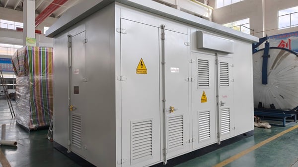
North America's electrical distribution infrastructure is undergoing significant transformation. Aging utility assets, expanding commercial developments, renewable energy integration, and the rapid deployment of electric vehicle (EV) charging networks are creating new requirements for reliable medium-voltage distribution equipment.
As utilities and developers invest in underground power distribution, IEEE standard pad-mounted transformers have become an essential component of modern electrical infrastructure.
Unlike conventional pole-mounted transformers, pad-mounted transformers are installed at ground level within secure, tamper-resistant enclosures. They provide an efficient connection between medium-voltage underground distribution systems and low-voltage electrical loads while supporting utility accessibility, public safety, and long-term serviceability.
For utility engineers, EPC contractors, electrical distributors, and commercial EV charging operators, selecting the right transformer requires more than matching voltage and kVA ratings. Engineers must evaluate applicable IEEE/ANSI standards, feed configurations, thermal performance, protection coordination, enclosure integrity, and site-specific operating conditions.
This technical guide explains the critical specifications and engineering considerations involved in selecting three-phase pad-mounted transformers for North American underground distribution and commercial EV charging projects.
1. Why Pad-Mounted Transformers Matter for North American Grid Modernization
1.1 The Growing Role of Underground Power Distribution
Underground power distribution is widely used in North American residential communities, commercial developments, industrial parks, and urban infrastructure projects.
Although underground distribution generally involves higher initial construction costs than overhead systems, it offers several advantages in suitable applications:
-
Reduced exposure of primary conductors to wind, falling branches, and certain weather-related hazards.
-
Improved visual appearance in commercial and residential developments.
-
Reduced overhead line clearance conflicts.
-
Flexible integration with commercial facilities and electrical infrastructure.
-
Ground-level equipment access for qualified utility personnel.
However, underground distribution does not eliminate outage risks. Cable faults, flooding, insulation deterioration, and equipment failures remain important engineering considerations.
Pad-mounted distribution transformers serve as critical interfaces between underground medium-voltage feeders and the secondary electrical systems supplying buildings, industrial equipment, and EV charging installations.
1.2 New Electrical Loads Are Changing Transformer Requirements
Traditional distribution networks were primarily designed around relatively predictable residential and commercial load profiles.
Today, utilities must accommodate more complex operating conditions, including:
-
High-density commercial developments.
-
Data centers and industrial facilities.
-
Distributed solar generation and battery energy storage systems.
-
Commercial EV charging plazas.
-
Electrified transportation fleets.
-
Increasing demand for monitoring and grid automation.
These applications introduce new considerations involving transformer capacity, load variability, thermal aging, voltage regulation, and protection coordination.
For example, a commercial charging site equipped with several 350 kW DC fast chargers may require substantially greater transformer capacity than a conventional retail facility.
As a result, transformer selection must consider both present electrical demand and realistic future expansion.
2. Understanding IEEE and ANSI Standards for Pad-Mounted Transformers
Compliance with applicable North American standards is one of the most important considerations when specifying a pad-mounted transformer.
The IEEE C57 family establishes requirements and guidance covering transformer construction, performance, testing, and application.
2.1 Key IEEE Standards for Pad-Mounted Distribution Transformers
| Standard | Main Scope | Engineering Relevance |
|---|---|---|
| IEEE C57.12.34 | Three-phase, 60 Hz, liquid-immersed pad-mounted distribution transformers | Electrical ratings, construction and performance requirements |
| IEEE C57.12.22 | Three-phase, 60 Hz, liquid-immersed pad-mounted distribution transformers with high-voltage bushings | Requirements for applicable transformer configurations |
| IEEE C57.12.28 | Pad-mounted equipment enclosure integrity | Tamper resistance, corrosion resistance and enclosure integrity |
| IEEE C57.12.00 | General requirements for liquid-immersed distribution, power and regulating transformers | General electrical and performance requirements |
| IEEE C57.12.90 | Test code for liquid-immersed transformers | Verification of electrical and dielectric performance |
| IEEE C57.91 | Loading guide for mineral-oil-immersed transformers | Thermal loading and insulation aging assessment |
| IEEE C57.12.70 | Terminal markings and connections | Connection identification and terminal arrangement |
Engineering note: IEEE C57.12.22 and IEEE C57.12.34 address different transformer configurations and are not interchangeable specifications. Engineers should confirm the applicable standard, edition, voltage class, and equipment arrangement before procurement.
2.2 Why IEEE C57.12.28 Enclosure Integrity Matters
Pad-mounted transformers are frequently installed in areas accessible to the public, including commercial parking lots, residential developments, and EV charging stations.
Consequently, enclosure design is a fundamental safety consideration.
IEEE C57.12.28 addresses enclosure integrity requirements for applicable pad-mounted equipment, including resistance to unauthorized entry and specified environmental conditions.
Important design considerations include:
-
Tamper-resistant compartment construction.
-
Secure access doors and locking provisions.
-
Corrosion-resistant materials and protective coatings.
-
Mechanical integrity of enclosure components.
-
Appropriate compartment separation and access arrangements.
For coastal installations, engineers should also evaluate salt exposure, humidity, coating performance, and long-term corrosion resistance.
Compliance with IEEE C57.12.28 should be supported by relevant design documentation and test evidence. Project-specific coating or salt-spray requirements may extend beyond the standard's minimum provisions.
2.3 UL, CSA, and Utility Approval Requirements
North American transformer procurement may involve several distinct compliance requirements.
These include IEEE/ANSI design standards, applicable safety certification or listing requirements, utility specifications, and local electrical codes.
A transformer designed according to IEEE standards is not automatically UL Listed or CSA Certified.
Likewise, compliance with a published standard does not necessarily guarantee acceptance by a particular utility.
Before purchasing, project teams should verify:
-
The applicable IEEE/ANSI standards and editions.
-
Utility-approved transformer configurations.
-
Required third-party certifications or evaluations.
-
Applicable U.S. Department of Energy efficiency requirements.
-
Canadian regulatory and provincial requirements, where relevant.
-
Factory test reports and supporting technical documentation.
For imported transformers, these requirements should be clarified during the RFQ stage rather than after equipment delivery.
3. Critical Specifications for Underground Distribution Transformers
Selecting an appropriate transformer involves coordinated decisions about electrical ratings, feeder arrangements, insulation systems, and protection devices.
3.1 Loop Feed vs. Radial Feed Pad-Mounted Transformers
Two common high-voltage connection arrangements are radial feed and loop feed.
Radial Feed Configuration
A radial-feed transformer receives power from a single primary feeder.
This arrangement is commonly used where the transformer is located at the end of a distribution circuit or where alternate feeder connections are unnecessary.
Advantages:
-
Relatively straightforward feeder arrangement.
-
Fewer primary cable connection points.
-
Suitable for independent commercial loads.
-
Potentially lower equipment and installation complexity.
However, a fault or interruption affecting the supplying feeder can interrupt service to downstream equipment.
Loop Feed Configuration
A loop-feed transformer provides primary cable connections that allow the distribution circuit to continue through the transformer location.
Depending on the utility network design and installed switching equipment, this configuration can support sectionalizing and alternate supply arrangements.
Advantages:
-
Greater flexibility in underground feeder design.
-
Support for utility switching and sectionalizing.
-
Potential for improved service restoration.
-
Suitable for commercial campuses and multi-transformer distribution systems.
Importantly, a loop-feed configuration does not automatically provide uninterrupted service. Redundancy depends on the overall network topology, switching scheme, and available alternate source.
| Selection Factor | Radial Feed | Loop Feed |
|---|---|---|
| Primary feeder arrangement | Single incoming supply | Incoming and outgoing feeder connections |
| Typical application | End-of-line loads | Multi-transformer underground networks |
| Installation complexity | Generally lower | Generally higher |
| Sectionalizing flexibility | Limited | Greater with suitable switching |
| Restoration capability | Dependent on upstream network | Can support alternate feeder restoration |
| Common applications | Small commercial facilities | Utility URD, campuses and commercial developments |
Selection recommendation: Utility distribution projects requiring feeder sectionalizing should evaluate loop-feed configurations, while independent commercial installations may benefit from radial-feed designs.
3.2 Transformer Capacity and Voltage Selection
Pad-mounted transformers are available across a wide range of ratings, depending on design, voltage class, cooling requirements, and manufacturer capabilities.
Common three-phase distribution transformer ratings include:
-
75 kVA
-
150 kVA
-
300 kVA
-
500 kVA
-
750 kVA
-
1,000 kVA
-
1,500 kVA
-
2,000 kVA
-
2,500 kVA
Higher-capacity custom designs may also be available, subject to applicable standards and project requirements.
Common North American medium-voltage systems include 13.8 kV, 24.94 kV, and 34.5 kV, although actual transformer winding ratings must match the utility's nominal system voltage and grounding arrangement.
Typical secondary voltage options include:
| Secondary Voltage | Common Applications |
|---|---|
| 208Y/120 V | Commercial buildings and smaller electrical loads |
| 480Y/277 V | Industrial facilities, large commercial buildings and EV charging infrastructure |
| 600Y/347 V | Certain Canadian commercial and industrial installations |
| Custom configurations | Utility-specific and industrial applications |
Voltage class selection must account for insulation coordination, basic impulse insulation level (BIL), grounding, and the utility's equipment specifications.
3.3 Dead-Front Design and Primary Protection
For underground distribution applications, dead-front transformer configurations are commonly specified.
Dead-front arrangements use insulated, separable primary connections to reduce exposure to energized components during authorized operations.
Typical accessories may include:
-
Loadbreak or deadbreak elbow connectors.
-
Primary bushings and bushing wells.
-
Surge arresters.
-
Bay-O-Net fuse assemblies.
-
Current-limiting backup fuses.
-
Oil temperature indicators.
-
Liquid level gauges.
-
Pressure relief devices.
-
Grounding provisions.
Protection equipment must be coordinated with upstream protective devices and downstream electrical loads.
The use of dead-front equipment does not eliminate electrical hazards. Switching, testing, and maintenance must follow the applicable utility procedures and electrical safety requirements.
4. Engineering Pad-Mounted Transformers for Commercial EV Fast Charging
Commercial EV charging infrastructure introduces operating characteristics that differ from those of many conventional distribution loads.
A transformer serving a DC fast-charging station must accommodate high power demand, charger conversion characteristics, potential load fluctuations, and future capacity expansion.
4.1 Calculating Transformer Capacity for DC Fast Charging
Consider a commercial EV charging plaza equipped with four 350 kW DC fast chargers.
The maximum combined DC output is:
4 × 350 kW = 1,400 kW
Assuming an illustrative charger efficiency of 95% and an AC-side power factor of 0.99:
Required apparent power:
Transformer kVA = 1,400 ÷ (0.95 × 0.99)
≈ 1,489 kVA
This example indicates that a 1,500 kVA transformer could be near its nominal rating when all four chargers operate at maximum output.
However, final transformer selection must also consider:
-
Charger manufacturer input specifications.
-
Simultaneous charging demand.
-
Site energy management and load-sharing controls.
-
Auxiliary equipment and facility loads.
-
Ambient temperature and installation conditions.
-
Transformer loading limits.
-
Future charging capacity expansion.
A 2,000 kVA transformer may provide additional capacity in some designs, but it should not be selected automatically without an engineering load assessment.
Oversizing also increases capital cost and can increase total no-load energy consumption, depending on transformer design.
4.2 Harmonic Distortion and Transformer Heating
DC fast chargers use power electronic converters to transform AC electrical power into regulated DC output.
These converters may introduce harmonic currents into the distribution system.
Harmonic currents can increase transformer winding eddy-current losses, stray losses, and operating temperatures.
The actual harmonic profile depends heavily on charger topology, power factor correction, filtering, and operating conditions.
Modern active-front-end chargers may exhibit relatively low input current distortion under specified operating conditions.
Therefore, engineers should not assume that every EV charging transformer requires a particular K-factor rating.
Instead, transformer selection should consider:
-
Charger input current harmonic spectrum.
-
Total harmonic current distortion (THDi).
-
IEEE 519 power quality considerations at the point of common coupling.
-
Transformer stray-loss and winding-loss characteristics.
-
Manufacturer thermal calculations.
-
Site-specific operating conditions.
K-factor-rated transformers are one possible approach for managing harmonic loading, but K-factor terminology is more commonly associated with certain dry-type transformer applications.
For liquid-filled pad-mounted transformers, a documented harmonic loss evaluation or application-specific thermal design may be more appropriate than specifying K-4 or K-13 without supporting calculations.
4.3 Dynamic Loading and Thermal Performance
EV charging demand can change as vehicles connect, disconnect, or adjust charging power.
Although charger power electronics generally control input current rather than producing uncontrolled motor-like starting currents, multiple high-power chargers can still create significant load changes.
Transformer thermal performance should therefore be evaluated using realistic charging demand profiles.
Key considerations include:
Winding hot-spot temperature: Excessive temperatures can accelerate insulation aging.
Top-oil temperature: Oil temperature provides an important indication of thermal operating conditions.
Load cycling: Repeated loading and cooling cycles affect transformer thermal behavior.
Ambient conditions: High summer temperatures and restricted airflow can reduce available thermal margins.
IEEE C57.91 provides guidance for evaluating loading and insulation aging in applicable mineral-oil-immersed transformers.
For large charging hubs, hourly or sub-hourly load profiles can support more accurate transformer sizing than a single maximum-demand estimate.
4.4 Energy Efficiency and No-Load Loss Reduction
EV charging stations may remain energized continuously even when charging demand is low.
Consequently, transformer no-load losses contribute to operating costs throughout the year.
Transformer designers commonly evaluate two core technologies:
Grain-Oriented Electrical Steel (GOES/CRGO)
Conventional grain-oriented electrical steel provides a widely established solution with predictable magnetic performance, manufacturing flexibility, and cost characteristics.
Amorphous Metal Cores
Amorphous core materials can substantially reduce no-load losses compared with certain conventional core designs.
However, actual performance depends on the complete transformer design, including core geometry, winding construction, operating flux density, and manufacturing processes.
Procurement teams should compare guaranteed no-load and load losses rather than relying solely on core material descriptions.
A comprehensive evaluation should consider total owning cost (TOC), including acquisition cost, no-load losses, load losses, electricity prices, and expected operating life.
4.5 Smart Monitoring for EV Charging Infrastructure
Large commercial EV charging hubs may benefit from transformer condition monitoring.
Depending on the application, monitoring provisions can include:
-
Oil temperature measurement.
-
Liquid level indication.
-
Pressure monitoring.
-
Load current measurement.
-
Temperature alarms.
-
Remote communication interfaces.
These functions can support preventive maintenance and improve operational visibility.
However, communication architecture, cybersecurity, utility integration, and remote monitoring requirements should be defined during project engineering.
5. Mineral Oil vs. Natural Ester Insulating Fluids
Insulating liquid selection influences transformer thermal behavior, fire safety considerations, maintenance requirements, and environmental performance.
Mineral oil remains widely used in liquid-immersed distribution transformers because of its established performance and cost characteristics.
Natural ester fluids offer an alternative for certain applications, particularly where enhanced fire safety or environmental considerations are important.
| Parameter | Mineral Oil | Natural Ester Fluid |
|---|---|---|
| Industry use | Widely established | Increasing use in selected applications |
| Fire point | Typically lower | Typically substantially higher |
| Biodegradability | Generally lower | Generally higher |
| Moisture behavior | Conventional mineral-oil characteristics | Different moisture absorption and insulation behavior |
| Initial fluid cost | Generally lower | Generally higher |
| Typical applications | Utility and commercial distribution | Fire-sensitive and environmentally sensitive installations |
Natural ester fluids can offer high-fire-point performance, but transformer design, fluid compatibility, maintenance procedures, and relevant fire protection requirements must be evaluated together.
For EV charging facilities located near buildings or public areas, engineers should review applicable fire codes, installation clearances, containment provisions, and utility requirements before selecting the insulating liquid.
A natural ester fluid should not be assumed to eliminate all fire protection or environmental compliance obligations.
6. Selecting a Pad-Mounted Transformer for North American Projects
For utility engineers and EPC procurement teams, a structured specification process can reduce technical ambiguity and prevent costly equipment mismatches.
6.1 Recommended Engineering Specification Checklist
| Specification | Information Required |
|---|---|
| Application | Utility distribution, commercial building, EV charging or industrial |
| Rated capacity | kVA/MVA |
| Frequency | 60 Hz |
| Primary voltage | Utility-specified nominal and winding voltage |
| Secondary voltage | 480Y/277 V, 208Y/120 V or other |
| Voltage class and BIL | According to utility and insulation coordination requirements |
| Feed configuration | Loop feed or radial feed |
| Primary termination | Dead-front or specified alternative |
| Insulating liquid | Mineral oil or approved alternative |
| Cooling arrangement | Applicable liquid-immersed cooling designation |
| Impedance | Project- and utility-specified percentage |
| Protection | Fuses, arresters and switching requirements |
| Enclosure | IEEE C57.12.28 requirements where applicable |
| Efficiency | Applicable DOE, Canadian or utility requirements |
| Monitoring | Temperature, pressure and communication provisions |
| Documentation | Drawings, test reports and compliance evidence |
6.2 Why Transformer Impedance Matters
Transformer impedance affects short-circuit current, voltage regulation, and protective device coordination.
A lower-impedance transformer may improve voltage regulation under certain loading conditions but can increase available fault current.
A higher-impedance transformer can reduce fault current while increasing voltage drop under load.
Therefore, impedance should be coordinated with the complete electrical system rather than selected independently.
For EV charging applications, engineers should evaluate voltage drop during high-demand operation and confirm that available fault current remains within the interrupting ratings of downstream equipment.
6.3 Factory Testing and Quality Documentation
Transformer quality assurance should include appropriate routine testing and documented inspection procedures.
Depending on the transformer type and applicable standard, factory testing may include:
-
Winding resistance measurements.
-
Ratio and polarity verification.
-
No-load losses and excitation current.
-
Load losses and impedance.
-
Applied-voltage dielectric testing.
-
Induced-voltage testing.
-
Leak testing for liquid-filled equipment.
Additional type, design, or special tests may be required by the purchaser.
Factory acceptance documentation should clearly identify the tested unit, applicable standards, acceptance criteria, and measured results.
For North American projects, buyers should also verify the availability of drawings, nameplate information, operating instructions, and documentation suitable for utility or authority review.
7. Jiangsu Dingxin Electric: Customized Pad-Mounted Transformer Solutions
Jiangsu Dingxin Electric is a power transformer manufacturer with more than 30 years of industry experience, serving international markets with distribution and power transformer solutions.
Its product portfolio includes:
-
Single-phase pole-mounted distribution transformers.
-
Oil-immersed distribution transformers.
-
Pad-mounted distribution transformers.
-
Dry-type distribution transformers.
-
Oil-immersed power transformers.
-
Prefabricated substations.
-
PV pad-mounted transformers.
For North American projects, Dingxin can work with customers to evaluate application-specific transformer requirements and develop customized equipment specifications.
7.1 Application-Oriented Transformer Engineering
Different projects require different electrical and mechanical configurations.
A utility underground distribution project may prioritize standardized primary connections, switching arrangements, and utility-approved accessories.
A commercial EV charging project may place greater emphasis on high-capacity secondary distribution, load-loss performance, harmonic evaluation, and thermal monitoring.
A renewable energy installation may introduce additional requirements involving bidirectional power flow, grounding, and protection coordination.
Dingxin's engineering discussions can address:
-
Project-specific voltage and capacity requirements.
-
Transformer winding and connection arrangements.
-
Enclosure dimensions and mechanical configuration.
-
Insulating liquid options.
-
Primary and secondary connection arrangements.
-
Monitoring and accessory requirements.
-
Factory testing and documentation expectations.
Final product availability and compliance must be confirmed against the agreed technical specification.
7.2 Supporting North American EPC and Distribution Projects
For international transformer procurement, technical communication is as important as manufacturing capability.
North American buyers should provide the intended application, utility specifications, applicable standards, and installation requirements early in the procurement process.
A complete technical RFQ helps clarify equipment compatibility and identify potential approval issues before production.
Dingxin supports discussions with utilities, EPC contractors, electrical equipment distributors, and commercial infrastructure developers seeking project-specific transformer solutions.
For projects requiring IEEE/ANSI configurations, compliance documentation and testing requirements should be established and verified before order confirmation.
8. Frequently Asked Questions About IEEE Pad-Mounted Transformers
What is an IEEE standard pad-mounted transformer?
An IEEE standard pad-mounted transformer is a ground-level distribution transformer designed according to applicable IEEE requirements for its electrical ratings, construction, testing, and enclosure configuration.
The relevant standards depend on the transformer type, voltage class, and application.
What is the difference between loop feed and radial feed pad-mounted transformers?
A radial-feed transformer receives power through a single primary feeder arrangement.
A loop-feed transformer provides connections that allow an underground distribution circuit to continue through the transformer location, supporting additional switching and sectionalizing options when properly designed.
What size transformer is needed for a commercial EV charging station?
Transformer capacity depends on charger power, AC input efficiency, power factor, simultaneous demand, auxiliary loads, and expansion plans.
For example, four 350 kW chargers operating simultaneously may require approximately 1,489 kVA of apparent power under illustrative 95% efficiency and 0.99 power factor assumptions.
Final sizing requires a detailed electrical load assessment.
Are IEEE C57.12.28 and IEEE C57.12.34 the same standard?
No. IEEE C57.12.28 addresses enclosure integrity requirements for applicable pad-mounted equipment.
IEEE C57.12.34 addresses requirements for specified three-phase liquid-immersed pad-mounted distribution transformers.
Both may be relevant to a particular transformer project, but they cover different requirements.
Can pad-mounted transformers use natural ester insulating fluid?
Yes. Certain liquid-filled pad-mounted transformers can be designed for natural ester insulating fluids.
The transformer must be engineered for the selected fluid, with appropriate consideration of material compatibility, thermal characteristics, dielectric performance, and applicable standards.
Do EV charging transformers require harmonic-rated designs?
Not necessarily.
Harmonic requirements depend on the charging equipment's input characteristics and the overall electrical system.
Engineers should evaluate the charger harmonic spectrum, transformer losses, and thermal operating conditions before specifying special harmonic-related design provisions.
9. Conclusion: Building Reliable Underground Distribution and EV Infrastructure
North America's grid modernization and commercial EV charging expansion are increasing demand for reliable, efficient, and application-specific pad-mounted distribution transformers.
For utilities, EPC contractors, and charging infrastructure developers, successful transformer selection depends on several interconnected factors:
-
Correct IEEE/ANSI standard selection.
-
Appropriate loop-feed or radial-feed configuration.
-
Accurate capacity and voltage matching.
-
Coordinated electrical protection.
-
Thermal and harmonic performance evaluation.
-
Suitable enclosure and insulating fluid design.
-
Verified factory testing and project documentation.
A properly specified transformer can improve distribution reliability, support long-term operating efficiency, and reduce installation and maintenance risks.
Request a Custom Pad-Mounted Transformer Specification
Planning an underground distribution upgrade or commercial EV fast-charging project in North America?
Jiangsu Dingxin Electric provides project-oriented transformer manufacturing and customization support for international utility and commercial power distribution applications.
Share your project voltage, required capacity, feed configuration, applicable standards, and technical drawings with our engineering team.
Contact Dingxin Electric to discuss your pad-mounted transformer requirements and request a customized technical quotation (RFQ).
Table of Contents
- 1. Why Pad-Mounted Transformers Matter for North American Grid Modernization
- 2. Understanding IEEE and ANSI Standards for Pad-Mounted Transformers
- 3. Critical Specifications for Underground Distribution Transformers
- 4. Engineering Pad-Mounted Transformers for Commercial EV Fast Charging
- 5. Mineral Oil vs. Natural Ester Insulating Fluids
- 6. Selecting a Pad-Mounted Transformer for North American Projects
- 7. Jiangsu Dingxin Electric: Customized Pad-Mounted Transformer Solutions
-
8. Frequently Asked Questions About IEEE Pad-Mounted Transformers
- What is an IEEE standard pad-mounted transformer?
- What is the difference between loop feed and radial feed pad-mounted transformers?
- What size transformer is needed for a commercial EV charging station?
- Are IEEE C57.12.28 and IEEE C57.12.34 the same standard?
- Can pad-mounted transformers use natural ester insulating fluid?
- Do EV charging transformers require harmonic-rated designs?
- 9. Conclusion: Building Reliable Underground Distribution and EV Infrastructure