 EN
EN
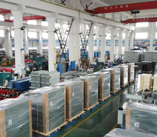
Transformers increase or decrease AC voltage through electromagnetic induction. Their output voltage is determined mainly by the ratio between the number of turns in the primary winding and the number of turns in the secondary winding.
If the secondary has more turns than the primary, the transformer steps the voltage up. If the secondary has fewer turns, it steps the voltage down.
Although the principle is simple, a practical transformer must also be designed for the required current, power rating, frequency, insulation, temperature rise, efficiency, and applicable safety standards.
What Is a Transformer?
A transformer is a passive electrical device that transfers energy between two or more windings through a changing magnetic field.
A conventional isolation transformer contains three main parts:
- Primary winding: connected to the input power source
- Secondary winding: supplies voltage to the load
- Magnetic core: provides a low-reluctance path for the alternating magnetic flux
The primary and secondary windings are normally electrically isolated but magnetically coupled through the core. This isolation can improve electrical safety and prevent a direct conductive connection between the input and output.
However, not every transformer provides isolation. An autotransformer, for example, uses a shared winding and therefore does not provide the same galvanic separation.
How Does a Transformer Work?
Transformer operation is based on Faraday’s law of electromagnetic induction. A changing magnetic flux through a coil induces an electromotive force across that coil.
The process can be understood in three stages.
1. The primary winding produces magnetic flux
When an alternating voltage is applied to the primary winding, it creates an alternating current. This current establishes a changing magnetic flux in the transformer core.
2. The core couples the magnetic flux
The magnetic core directs most of the changing flux through both windings. Core materials and construction methods are selected to provide effective magnetic coupling while limiting eddy-current and hysteresis losses.
3. The secondary winding develops a voltage
Because the changing core flux passes through the secondary winding, it induces a voltage across that winding. The induced voltage increases with the number of secondary turns.
This relationship follows directly from Faraday’s law and forms the basis of both step-up and step-down transformers. OpenStax University Physics provides a detailed derivation of the transformer equations.
The Transformer Turns-Ratio Formula
For an ideal transformer:
Vs / Vp = Ns / Np
Where:
- Vp = Primary input voltage
- Vs = Secondary output voltage
- Np = Number of turns in the primary winding
- Ns = Number of turns in the secondary winding
The voltage ratio is therefore equal to the winding turns ratio.
Step-up transformer
A transformer steps up voltage when:
Ns > Np
Therefore:
Vs > Vp
The secondary winding has more turns than the primary winding, so the secondary voltage is higher than the primary voltage.
Step-Down Transformer
A transformer steps down voltage when:
Ns < Np
Therefore:
Vs < Vp
The secondary winding has fewer turns than the primary winding, so the secondary voltage is lower than the primary voltage.
One-to-One Isolation Transformer
When the primary and secondary windings have approximately the same number of turns:
Ns = Np
Therefore:
Vs ≈ Vp
The output voltage is approximately equal to the input voltage.
Practical Step-Down Transformer Example
Suppose a transformer must convert 230 V AC to 24 V AC.
The required turns ratio is:
Ns / Np = Vs / Vp
Ns / Np = 24 / 230
Ns / Np ≈ 0.104
If the primary winding has 1,000 turns:
Ns = 1,000 × 0.104
Ns ≈ 104 turns
Therefore, the ideal secondary winding would have approximately 104 turns.
In a practical transformer, the manufacturer may add secondary turns to compensate for winding resistance and voltage drop under load.
Practical Step-Up Transformer Example
Suppose a transformer must increase the voltage from 120 V AC to 240 V AC.
The required turns ratio is:
Ns / Np = 240 / 120
Ns / Np = 2
If the primary winding has 500 turns:
Ns = 500 × 2
Ns = 1,000 turns
The secondary winding therefore requires approximately twice as many turns as the primary winding.
What Happens to Current?
A transformer changes current in the opposite direction to voltage.
For an ideal transformer, input power equals output power:
Vp × Ip = Vs × Is
Where:
- Vp = Primary voltage
- Ip = Primary current
- Vs = Secondary voltage
- Is = Secondary current
The current ratio is:
Is / Ip = Np / Ns
Therefore:
- Step-up transformer: voltage increases and available current decreases.
- Step-down transformer: voltage decreases and available current increases.
A transformer does not create additional energy. In a real transformer, output power is slightly lower than input power because of copper loss, core loss, and other losses.
Why Does the Low-Voltage Winding Use Thicker Wire?
A step-down transformer’s secondary winding normally carries more current than its primary winding. It therefore usually requires thicker wire.
The conductor size must be selected according to:
- RMS current
- Permitted current density
- Winding temperature
- Ambient temperature
- Duty cycle
- Cooling conditions
- Insulation thickness
- Available winding space
Using wire that is too thin increases resistance, voltage drop, copper loss, and winding temperature. Excessive temperature can shorten insulation life and create a safety risk.
In a step-up transformer, the higher-voltage winding typically uses more turns of thinner wire because it carries less current. The exact conductor size still requires an engineering calculation.
Why Are Transformers Used for Power Transmission?
For a given transmitted power, increasing voltage reduces current:
I = P / V
Where:
- I = Current
- P = Power
- V = Voltage
When voltage increases, the current required to transmit the same power decreases.
Because the current is squared in this equation, reducing current can greatly reduce conductor heating and transmission loss.
Power systems therefore use step-up transformers to increase generator voltage for long-distance transmission. Near the point of use, step-down transformers reduce the voltage to suitable distribution and utilization levels. The U.S. Department of Energy similarly explains that high-voltage transmission reduces the current required and decreases line losses. U.S. Department of Energy
Can a Transformer Operate on DC?
A conventional transformer requires changing magnetic flux and therefore cannot continuously transform steady DC voltage.
If steady DC is applied directly to a standard transformer winding:
- There is no continuous transformer action after the initial transient.
- The winding current may become dangerously high.
- The core can saturate.
- The winding may overheat or fail.
Electronic power supplies can convert DC voltage by first switching it at a controlled frequency. The resulting alternating waveform can then drive a high-frequency transformer or coupled inductor. This is how many flyback, forward, push-pull, half-bridge, and full-bridge converters operate.
The important distinction is that a conventional transformer does not transform steady DC directly; the DC must first be electronically switched.
Ideal Equations vs. Real Transformer Performance
The turns-ratio equation describes an ideal transformer. Real transformers have losses and voltage drops.
Copper loss
The resistive power loss in a conductor is:
Power loss = I² × R
For maximum WordPress compatibility, this can also be written as:
Power loss = I × I × R
Where:
- I = Current flowing through the conductor
- R = Conductor resistance
Because current is squared in this calculation, reducing the current can significantly reduce transmission-line losses.
Core loss
An alternating magnetic field causes hysteresis and eddy-current losses in the core. Core loss is affected by:
- Core material
- Operating frequency
- Applied voltage
- Number of primary turns
- Core cross-sectional area
- Magnetic flux density
- Lamination thickness
Leakage flux
Not all magnetic flux links both windings. Leakage flux affects voltage regulation and can produce electromagnetic interference.
No-load current
Even with no secondary load, the primary draws current to magnetize the core and supply core losses.
Temperature rise
Copper and core losses generate heat. A transformer must remain within the temperature limits of its insulation system under the specified load and ambient conditions.
Voltage regulation
The output voltage normally decreases between no-load and full-load conditions because of internal impedance.
Voltage regulation can be expressed as:
Voltage regulation (%) = [(Vno-load − Vfull-load) / Vfull-load] × 100
For this reason, manufacturers may design the no-load secondary voltage slightly above the rated output voltage.
Does Frequency Affect Transformer Design?
Yes. Frequency is a critical design parameter.
For a sinusoidal waveform, the approximate RMS voltage per winding is related to frequency, turns, core area, and maximum flux density by:
V = 4.44 × f × N × A × Bmax
Where:
- V = RMS winding voltage
- f = Operating frequency in hertz
- N = Number of winding turns
- A = Effective core cross-sectional area
- Bmax = Maximum magnetic flux density
A 60 Hz transformer should not automatically be operated at 50 Hz at the same voltage. The lower frequency can increase magnetic flux density, which may lead to core saturation, excessive current, noise, and overheating.
The manufacturer must know the actual input frequency and voltage range before finalizing the design.
How to Specify a Step-Up or Step-Down Transformer
A professional transformer specification should include more than input and output voltage.
Provide the following information when requesting a design or quotation:
- Nominal input voltage
- Minimum and maximum input voltage
- Input frequency
- Required output voltage or voltages
- Continuous output current
- Peak current and duration
- Load type
- Required VA rating
- Duty cycle
- Maximum dimensions
- Mounting method
- Lead-wire or terminal requirements
- Ambient temperature
- Cooling and enclosure conditions
- Maximum permitted temperature rise
- Insulation class
- Dielectric-strength requirements
- Required electrostatic or magnetic shielding
- Thermal fuse or thermal protector requirements
- Target country or market
- Applicable safety and environmental requirements
- Estimated production quantity
Providing complete operating conditions helps prevent incorrect sizing and improves voltage regulation, reliability, and service life.
Frequently Asked Questions
Does a step-up transformer increase power?
No. A step-up transformer increases voltage but reduces available current. Its output power is always slightly lower than its input power because a real transformer has copper, core, and other losses.
Does a step-down transformer always provide more current?
It can provide a higher rated secondary current for the same approximate power level, but the actual current is determined by the connected load and the transformer’s rated capacity. A transformer does not force its maximum current into the load.
Are the primary and secondary windings connected?
In an isolation transformer, they are electrically separate and coupled through the magnetic core. In an autotransformer, part of the winding is shared, so there is no equivalent galvanic isolation.
Can one transformer provide several output voltages?
Yes. A transformer can use multiple secondary windings, center-tapped windings, or winding taps to provide different voltage outputs.
How do I calculate transformer VA?
For a simple single-secondary AC transformer:
VA = Vs × Is
Where:
- VA = Transformer apparent-power rating
- Vs = Rated secondary voltage
- Is = Rated secondary current
Example:
Secondary voltage = 24 V AC
Secondary current = 5 A
VA = 24 × 5
VA = 120 VA
For multiple secondaries, the required total VA is calculated from the combined winding loads, with appropriate consideration for load type, duty cycle, efficiency, regulation, rectification, and temperature rise.
Custom Step-Up and Step-Down Transformers from Dingxin
Dingxin manufactures custom transformers, including transformer solutions for customers and equipment intended for the European market.
Transformers can be developed according to specified electrical, mechanical, thermal, and application requirements, including:
- Custom input and output voltages
- Step-up and step-down designs
- Multiple secondary windings
- EI and toroidal constructions
- 50 Hz and 60 Hz applications
- Customized VA ratings
- Lead wires, terminals, brackets, and mounting options
- Electrostatic shielding
- Thermal fuses and thermal protectors
- Application-specific insulation systems
- Designs based on the customer’s target-market requirements
Final compliance and certification requirements should be confirmed during the engineering process according to the transformer design, intended equipment, and destination market.
Request a Custom Transformer Design
Need a transformer with a specific voltage ratio, power rating, size, temperature limit, or installation method?
Send Dingxin the following information:
- Input voltage and frequency
- Required output voltage and current
- Continuous and peak load conditions
- Maximum dimensions
- Mounting and connection requirements
- Operating temperature
- Target market and compliance requirements
- Estimated order quantity
Contact Dingxin today to request a technical review, custom transformer design, sample, or quotation.
Table of Contents
- What Is a Transformer?
- How Does a Transformer Work?
- The Transformer Turns-Ratio Formula
- Practical Step-Down Transformer Example
- Practical Step-Up Transformer Example
- What Happens to Current?
- Why Does the Low-Voltage Winding Use Thicker Wire?
- Why Are Transformers Used for Power Transmission?
- Can a Transformer Operate on DC?
- Ideal Equations vs. Real Transformer Performance
- Does Frequency Affect Transformer Design?
- How to Specify a Step-Up or Step-Down Transformer
- Frequently Asked Questions
- Custom Step-Up and Step-Down Transformers from Dingxin
- Request a Custom Transformer Design