Tel: +86-513-88779999
Email: [email protected]
Tel: +86-513-88779999
Email: [email protected]
As solar photovoltaic (PV), wind power, and battery energy storage systems (BESS) continue to expand, renewable energy developers face increasing pressure to optimize electrical infrastructure.
Transformer substations must meet demanding electrical requirements while minimizing installation space, supporting efficient maintenance, and helping projects achieve their construction schedules.
Traditionally, buyers have compared European-type and American-type substations based on structural differences. European-style prefabricated substations generally feature separate compartments for medium-voltage equipment, transformers, and low-voltage distribution systems. American-style combined transformer units typically integrate selected switching and protection functions into a compact transformer-centered design.
However, modern renewable energy substation selection requires more than choosing between European and American configurations.
The more important questions are how electrical equipment should be integrated, which functions can be standardized, how maintenance access should be maintained, and whether the complete substation can meet the project's operating requirements.
This is where compact and modular transformer substations become increasingly important.
As a power transformer and prefabricated substation manufacturer, Dingxin Electric provides customized transformer and substation solutions for solar, wind, industrial power distribution, and renewable energy infrastructure projects.
This guide examines the engineering principles behind compact and modular substations, their applications in renewable energy systems, and the technical considerations that project developers should evaluate before procurement.
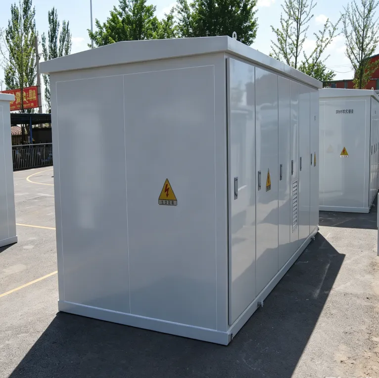
European-type and American-type substations represent two familiar approaches to transformer and distribution equipment integration.
However, these classifications do not fully describe the engineering requirements of modern renewable energy projects.
European-type prefabricated substations typically use compartmentalized construction.
Medium-voltage switchgear, the distribution transformer, and low-voltage equipment are located in separate functional areas within an integrated enclosure.
This arrangement offers flexibility for electrical configuration, maintenance access, and equipment replacement.
It is particularly suitable when projects require multiple outgoing feeders, dedicated protection systems, or more extensive distribution equipment.
American-type combined transformer units generally adopt a more integrated structure.
Selected switching and protection components may be incorporated into the transformer assembly, producing a compact equipment arrangement.
Such designs are useful for decentralized distribution networks and applications requiring relatively straightforward electrical connections.
However, the term "American-type" does not automatically imply compliance with North American IEEE or ANSI requirements. Equipment specifications and applicable standards must be evaluated separately.
Solar and wind projects often require equipment that performs more than conventional voltage distribution.
A renewable energy substation may need to accommodate:
Transformer step-up from inverter or converter output voltage to medium-voltage collection levels.
Multiple generator or inverter connection points.
Medium-voltage switching and electrical protection.
Grid connection and utility interface requirements.
Communication and monitoring systems.
Outdoor installation under challenging environmental conditions.
Specialized operating conditions, including harmonics and variable loading.
Therefore, selecting a renewable energy substation should begin with the electrical architecture and operating requirements, rather than the enclosure's regional design classification.
The goal is to develop a coordinated solution that balances electrical performance, equipment integration, installation efficiency, and long-term maintainability.
A compact modular transformer substation is a coordinated electrical system that combines voltage transformation, switching, protection, and associated functions using an optimized physical arrangement.
The terms "compact," "modular," and "prefabricated" are related but have different meanings.
Compact design focuses on reducing equipment footprint and optimizing the arrangement of components.
It may involve:
Efficient transformer and switchgear positioning.
Optimized cable routing.
Reduced spacing between compatible equipment compartments.
Integrated protection and monitoring equipment.
Coordinated ventilation and cooling.
Enclosures designed for the available installation area.
However, compact construction must not compromise electrical clearances, operating safety, thermal performance, or maintenance accessibility.
Modular construction involves dividing a substation into defined functional units with coordinated interfaces.
Depending on project requirements, these modules may include:
Transformer Module: An oil-immersed or dry-type transformer selected according to capacity, voltage ratio, loading conditions, and application requirements.
Medium-Voltage Module: Switchgear, ring main units, circuit breakers, protection devices, and cable termination equipment.
Low-Voltage Module: Distribution switchgear, busbars, protective devices, and outgoing feeder connections.
Control and Monitoring Module: Metering, protective relays, communication equipment, and monitoring interfaces.
Auxiliary Module: Equipment supporting ventilation, temperature monitoring, lighting, auxiliary power, or other required functions.
Not every renewable energy substation includes all these modules. The configuration depends on the electrical system architecture.
A prefabricated substation is assembled and integrated substantially at the factory before delivery.
Factory prefabrication can include equipment installation, internal electrical connections, enclosure assembly, and defined inspection and testing activities.
However, prefabrication is not identical to modularity.
A prefabricated substation may use a highly customized arrangement, while a modular system may use standardized equipment interfaces across multiple projects.
| Design Approach | Primary Objective | Key Characteristics |
|---|---|---|
| Compact design | Reduce equipment footprint | Optimized physical layout |
| Modular design | Improve configuration flexibility | Defined functional units and interfaces |
| Factory prefabrication | Reduce field assembly | Factory-installed and coordinated equipment |
| Project customization | Match technical specifications | Application-specific engineering |
| Integrated substation | Coordinate multiple electrical functions | Combined transformation, switching, and protection |
A well-engineered renewable energy substation may incorporate all five approaches, but they should not be treated as interchangeable.
Reducing physical dimensions can improve site utilization, particularly in solar plants, industrial facilities, and distributed energy projects.
However, the smallest possible enclosure is not necessarily the best engineering solution.
Compact substations must maintain appropriate space for electrical insulation, heat dissipation, equipment operation, and future maintenance.
Transformers generate heat during operation because of no-load and load losses.
Additional heat may be produced by switchgear connections, busbars, power electronics, and auxiliary components.
When equipment is installed inside a compact enclosure, limited airflow and heat accumulation can increase operating temperatures.
Important design considerations include:
Transformer total losses under rated operating conditions.
Natural or forced ventilation requirements.
Internal airflow distribution.
Ambient temperature and solar radiation.
Heating from neighboring electrical equipment.
Enclosure materials and thermal characteristics.
Temperature monitoring and protective functions.
For solar and wind applications, temperature variation and outdoor exposure make thermal assessment particularly important.
An enclosure that performs adequately under moderate conditions may require additional engineering evaluation in a high-temperature or high-altitude environment.
Consequently, enclosure dimensions should be determined through coordinated thermal and electrical design rather than reduced solely to meet a footprint target.
Compact electrical equipment must maintain the insulation distances and dielectric performance required by its voltage rating and construction.
The internal arrangement should consider:
Rated insulation levels.
Power-frequency and impulse withstand requirements.
Phase-to-phase and phase-to-earth insulation.
Cable termination arrangements.
Equipment separation.
Grounding and bonding.
Applicable internal arc safety requirements.
Reducing enclosure dimensions without reviewing these factors can compromise electrical performance.
Maintenance access is another critical factor.
A compact substation must provide sufficient space for authorized personnel to inspect, operate, isolate, and service the installed equipment safely.
Important questions include:
Can operators access switching devices without obstruction?
Are required safety clearances maintained?
Can transformer components be inspected or replaced?
Is there adequate space for cable termination work?
Can major equipment be removed without extensive structural modification?
Are access doors and ventilation openings positioned correctly?
Compact substations should therefore be designed around the complete equipment lifecycle, not only transportation and initial installation.
A smaller enclosure does not automatically produce a smaller total installation area.
The overall site layout must also account for cable trenches, foundations, maintenance clearances, access routes, fire separation, and local safety requirements.
For renewable energy projects, engineering teams should compare the complete installed footprint, rather than enclosure dimensions alone.
Renewable energy projects often involve multiple electrical equipment suppliers, contractors, and installation teams.
Transformer manufacturers, inverter suppliers, switchgear suppliers, system integrators, and EPC contractors must coordinate electrical and mechanical interfaces.
Modular engineering can simplify parts of this process when interfaces are clearly defined.
Standardized modules may use predefined transformer ratings, switchgear arrangements, enclosure designs, and connection interfaces.
For projects with repeated electrical blocks, this approach can reduce the need to redesign every substation from the beginning.
Potential benefits include:
More consistent engineering documentation.
Repeatable manufacturing processes.
Simplified equipment coordination.
Easier spare-part planning.
Reduced variation between installation units.
However, standardized equipment must still satisfy the electrical and environmental requirements of each project.
Factory prefabrication allows selected electrical and mechanical assembly activities to be completed before shipment.
Depending on equipment scope, these activities can include transformer installation, switchgear positioning, cable or busbar connections, control wiring, enclosure assembly, and functional checks.
This can reduce some on-site installation activities and improve the consistency of equipment interfaces.
Nevertheless, foundations, external cable connections, site grounding, commissioning, and utility approval may still be required.
Factory assembly does not eliminate the need for site acceptance testing.
Renewable energy installations frequently differ in rated power, system voltage, protection architecture, environmental exposure, and monitoring requirements.
For this reason, a completely standardized design is not always appropriate.
A practical approach is to combine repeatable manufacturing methods with project-specific engineering.
For example, a manufacturer may use established transformer construction and enclosure design principles while customizing the voltage ratio, impedance, winding configuration, cooling arrangement, and switchgear interfaces.
Poorly coordinated interfaces can create delays even when individual electrical components have been manufactured correctly.
Critical interfaces include:
Transformer-to-inverter connections.
Transformer-to-medium-voltage switchgear connections.
Cable termination dimensions and types.
Protection and control wiring.
Grounding and bonding arrangements.
Communication protocols.
Equipment mounting and transportation interfaces.
A modular substation should have clearly defined interface documents and responsibilities before production begins.
Solar PV plants typically use inverters to convert photovoltaic DC power into AC electricity.
The inverter output voltage is then increased through a step-up transformer before connection to the medium-voltage collection network.
Depending on plant design, collection voltages may include 10 kV, 20 kV, 33 kV, or 35 kV.
A solar generation block may follow this power flow:
PV Arrays → Solar Inverters → Step-Up Transformer → MV Switchgear → Collection Network
Some projects locate the inverter and transformer separately.
Others use a coordinated inverter-transformer station with equipment installed on a common skid or within integrated enclosures.
The choice depends on the electrical architecture, site conditions, equipment compatibility, and installation requirements.
A solar step-up transformer should be selected based on:
Rated apparent power: The transformer must accommodate the inverter's maximum operating apparent power, including applicable reactive power requirements.
Voltage ratio: The low-voltage winding must match the inverter output, while the medium-voltage winding must match the collection network.
Impedance: Transformer impedance affects fault current, voltage regulation, and system coordination.
Harmonic performance: The expected inverter harmonic spectrum should be evaluated for its effect on additional transformer losses and heating.
Insulation coordination: The design should consider switching transients, overvoltage protection, and applicable electrical insulation requirements.
Thermal performance: The expected loading profile and outdoor ambient conditions should be considered.
For suitable projects, an integrated solar step-up transformer station can provide:
Coordinated transformer and switchgear installation.
Compact equipment positioning.
Reduced field assembly requirements.
Defined electrical interfaces.
Standardized arrangements across repeated solar generation blocks.
However, these benefits depend on suitable cooling, maintenance accessibility, and successful system integration.
A compact enclosure should not be selected solely because it occupies less ground area.
Wind power projects require transformer solutions capable of operating under variable generation conditions and demanding environmental exposure.
The transformer may be installed near the turbine, at its base, or within a separate equipment enclosure.
A wind turbine step-up transformer raises the generator or converter output voltage to the wind farm collection voltage.
The electrical design must consider the wind turbine's power conversion equipment, operating profile, protection scheme, and collection network.
In addition to conventional transformer requirements, important factors may include:
Variable load cycles.
Harmonic currents from converter equipment.
Switching transients.
Temperature fluctuations.
Moisture and corrosion exposure.
Mechanical vibration.
Transportation and installation restrictions.
IEC/IEEE 60076-16 provides specific requirements for transformers used in wind turbine step-up applications within its defined scope.
Compact transformer arrangements can be valuable where equipment space is restricted.
However, reduced dimensions must not compromise insulation performance, cooling, structural integrity, or maintenance access.
The transformer and surrounding electrical equipment should be designed as part of the complete wind turbine electrical system.
A modular approach may allow manufacturers and project engineers to coordinate transformer design with medium-voltage protection, cable connections, monitoring, and enclosure arrangements.
For wind projects involving multiple turbines, consistent equipment interfaces can simplify manufacturing and installation planning.
Battery energy storage systems introduce additional requirements because their transformers may operate with bidirectional active power flow.
During charging, electrical power flows toward the battery PCS.
During discharge, power flows from the PCS toward the connected electrical network.
Transformer selection should consider:
Maximum PCS apparent power.
Charging and discharging duty cycles.
Harmonic current spectrum.
Reactive power operating requirements.
Transformer thermal performance.
Protection coordination.
Grounding arrangements.
Grid interconnection requirements.
Although power transformers can transfer AC power in either direction, the complete system must be designed to accommodate the intended operating modes.
Some BESS projects use coordinated PCS-transformer equipment packages.
Depending on the configuration, the transformer, PCS, medium-voltage switchgear, and auxiliary equipment may be arranged as adjacent modules or installed within coordinated enclosures.
The suitability of this architecture depends on thermal requirements, electrical clearances, fire safety, maintenance access, and equipment interfaces.
In hybrid renewable energy projects, transformer requirements depend on whether the solar PV and BESS systems share a common AC connection or use separate transformer paths.
Engineers must evaluate:
Maximum simultaneous power transfer.
Import and export operating scenarios.
Protection settings under different power flow conditions.
Voltage regulation.
Transformer loading and cooling.
Monitoring and control integration.
These factors determine whether a shared transformer arrangement or separate transformer modules are more appropriate.
A modular substation is more than a collection of individually tested electrical components.
The complete assembly introduces additional electrical, thermal, mechanical, and operational interactions.
For example, a transformer may satisfy its individual temperature-rise requirements while experiencing different cooling conditions after installation inside an enclosure.
Similarly, switchgear performance can be affected by the final equipment arrangement, cable connections, and surrounding structures.
Therefore, complete substation verification is a critical part of integrated equipment engineering.
For applicable prefabricated substations, IEC 62271-202:2022 addresses service conditions, rated characteristics, general structural requirements, and test methods.
Other relevant standards may include:
| Standard | Engineering Relevance |
|---|---|
| IEC 62271-202 | AC prefabricated substations |
| IEC 60076 series | Power transformer design and testing |
| IEC/IEEE 60076-16 | Wind turbine step-up transformers |
| IEC 62271 series | Medium-voltage switchgear and controlgear |
| IEC 61439 series | Applicable low-voltage assemblies |
| IEEE C57 series | Applicable power and distribution transformer requirements |
Applicable standards depend on equipment construction, destination market, and project specifications.
Integrated equipment arrangements may affect ventilation and heat dissipation.
Thermal evaluation should therefore consider the complete enclosure, including transformer losses, neighboring electrical equipment, airflow restrictions, and solar radiation.
For relevant prefabricated substation designs, IEC 62271-202 includes provisions addressing temperature-rise performance and the influence of solar radiation.
The integrated arrangement should be reviewed for adequate insulation coordination and dielectric performance.
Verification may include applicable dielectric tests, inspection of clearances, grounding continuity, and checks of electrical connections.
The exact test scope depends on the equipment configuration and relevant standards.
Switching, protection, and control functions should be verified against the approved system design.
Depending on the project, checks may include:
Protective relay settings and functionality.
Switching interlocks.
Control and alarm circuits.
Communication interfaces.
Auxiliary power systems.
Monitoring equipment.
Equipment labeling and operating instructions.
Factory Acceptance Testing (FAT) should confirm that the assembled substation meets the agreed technical specification.
A project-specific FAT plan may include dimensional inspection, wiring verification, functional testing, applicable routine tests, and review of equipment documentation.
However, routine testing of individual components does not automatically demonstrate compliance of the complete integrated substation.
Applicable assembly-level design verification, type testing, or other required evidence should be identified before production.
Factory verification must be followed by appropriate site inspection and commissioning.
Site activities may include external cable testing, grounding verification, protection coordination checks, functional testing, and utility acceptance procedures.
The exact requirements depend on local regulations and the project-specific commissioning plan.
The following comparison helps project developers evaluate different substation approaches.
| Selection Factor | Conventional Separate Equipment | Compact Integrated Substation | Modular Prefabricated Substation |
|---|---|---|---|
| Equipment layout | Individually installed | Optimized integrated layout | Defined functional modules |
| Equipment footprint | Often larger | Potentially smaller | Depends on configuration |
| Factory integration | Varies | Generally high | Generally high |
| Site assembly | Often more extensive | Potentially reduced | Potentially reduced |
| Configuration flexibility | High | May be limited by integration | Depends on module interfaces |
| Maintenance access | Individual equipment access | Requires careful compact design | Depends on module arrangement |
| Future modification | Often flexible | May be more restricted | Depends on standardization |
| Thermal engineering | Equipment-specific and site-level | Requires integrated assessment | Requires module and assembly assessment |
| Project delivery | Multiple equipment interfaces | Consolidated equipment interfaces | Repeatable interfaces where standardized |
| Best application | Complex or highly customized projects | Space-constrained installations | Repeated or configurable project blocks |
This comparison represents general design tendencies, not guaranteed performance differences.
Project-specific engineering, testing, and cost analysis are necessary before selecting a final configuration.
A compact modular substation may reduce selected installation activities, but purchase price and physical dimensions should not be the only decision factors.
The overall evaluation should include project capital expenditure, operation and maintenance, and expected equipment service life.
Initial cost depends on transformer rating, switchgear configuration, enclosure construction, monitoring requirements, and customization.
A compact design is not automatically less expensive, particularly if additional thermal management or specialized components are required.
Prefabricated substations may simplify installation by reducing separate equipment handling and field connections.
However, larger integrated assemblies can introduce transportation restrictions, lifting requirements, and special foundation considerations.
The logistics plan should therefore be reviewed alongside the electrical layout.
Restricted access, difficult component replacement, or limited spare-part availability may increase long-term operating costs.
Equipment maintainability should be evaluated during initial design rather than after installation.
Transformer no-load and load losses contribute to operating costs over the equipment's service life.
For renewable energy installations operating over many years, evaluating transformer efficiency and actual loading profiles can be more important than small differences in initial purchase price.
Factory integration can reduce selected site assembly tasks and improve interface coordination.
However, overall delivery time also depends on engineering approvals, manufacturing lead time, transportation, civil works, grid connection, and commissioning.
Percentage reductions in construction time should be supported by comparable project data rather than assumed from the use of modular equipment.
Jiangsu Dingxin Electric Co., Ltd. is a manufacturer of power transformers, distribution transformers, and prefabricated substations serving utility, industrial, and renewable energy projects.
With more than 30 years of experience in electrical equipment manufacturing, Dingxin provides transformer solutions for a wide range of power transformation and distribution applications.
Dingxin manufactures and supplies products including:
Oil-Immersed Distribution Transformers
Dry-Type Distribution Transformers
Pad-Mounted Distribution Transformers
Prefabricated Transformer Substations
Photovoltaic Combined Transformers
Wind Power Transformer Solutions
Power Transformers
Customized Distribution Equipment
These products support applications where voltage transformation, electrical reliability, and installation suitability are important.
Dingxin can review technical requirements involving:
Transformer capacity and voltage ratio: Selection according to the power conversion equipment and electrical collection network.
Impedance and winding configuration: Engineering coordination with short-circuit, grounding, and protection requirements.
Cooling and thermal performance: Evaluation of transformer operating conditions and installation environment.
Insulation requirements: Selection according to system voltage, equipment insulation levels, and applicable standards.
Enclosure and equipment layout: Coordination of transformer dimensions, equipment interfaces, and maintenance requirements.
For renewable energy projects, Dingxin's prefabricated substation and combined transformer product range provides a basis for developing application-specific equipment arrangements.
Depending on the project, customization may involve transformer ratings, switchgear interfaces, enclosure construction, protection requirements, monitoring arrangements, and installation conditions.
The complete scope of integration, including any third-party inverter or PCS equipment, should be confirmed during technical evaluation.
Dingxin emphasizes transformer manufacturing quality, engineering review, and production control.
For international EPC and electrical infrastructure projects, technical coordination can include review of drawings, project specifications, applicable standards, factory inspection requirements, and shipment documentation.
The objective is to provide transformer and substation solutions that match the electrical application rather than simply offering a standardized equipment enclosure.
Before sending an RFQ to a transformer manufacturer, project engineers should prepare the main electrical and mechanical requirements.
| Specification | Information to Provide |
|---|---|
| Project application | Solar PV, wind power, BESS, or hybrid energy |
| Transformer rating | Required kVA or MVA |
| Low-voltage rating | Inverter, PCS, or generator AC voltage |
| Medium-voltage rating | Collection network voltage |
| Frequency | 50 Hz or 60 Hz |
| Transformer configuration | Oil-immersed or dry-type |
| Winding connection | Required vector group and grounding |
| Impedance | Required percentage or design range |
| Switching arrangement | MV switching and protection requirements |
| Equipment interfaces | Inverter, PCS, switchgear, and cable connections |
| Environmental conditions | Temperature, altitude, humidity, corrosion |
| Installation restrictions | Available area, transport dimensions, lifting |
| Maintenance requirements | Access, component replacement, operating procedures |
| Monitoring | Required measurements, alarms, and communication |
| Applicable standards | IEC, IEEE, or utility-specific requirements |
| Verification requirements | FAT, type-test evidence, site acceptance requirements |
Providing a single-line diagram, equipment layout, and technical specification can improve engineering coordination and quotation accuracy.
Compact substations focus on reducing physical equipment dimensions. Modular substations use defined functional units and coordinated interfaces to support configurable equipment arrangements. A modular substation may also be compact, but the terms describe different engineering characteristics.
No. Prefabrication refers to factory assembly, while modularity refers to the use of defined functional units. A prefabricated substation may be customized without using standardized modules.
Yes. Compact transformer substations can be suitable for solar installations when the equipment meets the required transformer capacity, voltage ratio, thermal performance, protection, and grid connection requirements.
Modular engineering can simplify configuration, manufacturing coordination, and repeated project installations through standardized functional interfaces. Its actual advantages depend on the degree of standardization and project requirements.
No. Reduced enclosure dimensions may lower some site-related costs, but compact designs can also require more demanding thermal management, specialized equipment arrangements, or additional maintenance provisions.
Engineers evaluate equipment losses, ambient conditions, ventilation arrangements, enclosure geometry, and the thermal interaction between components. Appropriate temperature-rise verification may also be required.
Individual component tests do not necessarily demonstrate the performance of the complete assembled substation. Integration can influence thermal behavior, dielectric performance, protection, and operational safety.
IEC 62271-202:2022 is an important standard for applicable AC prefabricated substations with rated voltages above 1 kV and up to and including 52 kV. Other transformer, switchgear, and local utility standards may also apply.
Yes. Modular substations can support BESS applications when transformer ratings, bidirectional loading, PCS interfaces, protection requirements, and installation conditions are properly coordinated.
Dingxin Electric manufactures transformers and prefabricated substation equipment for renewable energy applications. Project-specific configurations can be evaluated according to transformer capacity, voltage levels, electrical interfaces, environmental conditions, and applicable technical standards.
The evolution of renewable energy substations is not simply a transition from European-type or American-type equipment toward smaller enclosures.
It represents a broader shift toward application-driven engineering, coordinated equipment integration, repeatable manufacturing, and lifecycle-oriented design.
Compact substations can improve space utilization, but reduced dimensions must be balanced against cooling, insulation, maintenance access, and operational safety.
Modular construction can improve configuration flexibility and project delivery, provided that equipment interfaces and responsibilities are clearly defined.
Factory prefabrication can simplify selected installation activities, but complete assembly performance and site commissioning remain essential.
For solar PV, wind power, and battery storage projects, the best transformer substation is the one that meets the electrical system's operating requirements while delivering reliable performance throughout its service life.
Dingxin Electric supports renewable energy developers, EPC contractors, and electrical engineering companies with customized transformer and prefabricated substation manufacturing solutions.
Whether your project requires a solar step-up transformer, wind power combined transformer, pad-mounted transformer, or prefabricated substation, Dingxin can review your technical specifications and discuss an appropriate equipment configuration.
Contact Dingxin Electric to discuss your electrical requirements and request a customized technical quotation.
Website: https://www.dingxinelectric.com/
Email: [email protected]
WhatsApp: +86 19901941814
Dingxin Electric — Power Transformer & Prefabricated Substation Manufacturer for Renewable Energy Projects.

Jiangsu Dingxin Electric, a high-tech power equipment manufacturer, produces high-quality transformers and substations, serving global markets across 30+ countries.
Room 118, Building 8, 2999 Hutai Road, Baoshan District, Shanghai, China


Copyright © Jiangsu Dingxin Electric Co., Ltd. All Rights Reserved | Privacy Policy
 EN
