
 EN
EN
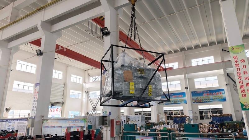
A 110 kV oil-immersed power transformer performs a critical role in voltage conversion and bulk power transmission. However, the transformer cannot be considered separately from the grounding arrangement of the electrical network.
The transformer neutral grounding system influences:
- Ground-fault current
- Temporary and transient overvoltage
- Protection sensitivity and selectivity
- Transformer insulation requirements
- System stability
- Personnel and equipment safety
For this reason, neutral grounding is not simply an accessory selection. It must be coordinated with the transformer winding connection, system grounding philosophy, insulation level, protection scheme and substation grounding grid.
This article explains the main functions, components and engineering considerations of a neutral grounding system for a 110 kV oil-immersed transformer.
Important: The appropriate neutral grounding method must be determined by the system operator and qualified power-system engineers. It must not be selected solely from the transformer voltage rating.
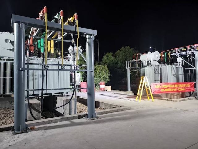
What Is the Neutral Point of a 110 kV Transformer?
When a three-phase transformer winding is connected in star, or wye, the three winding ends are joined at a common point. This connection is called the neutral point and is normally identified by the letter N.
The neutral provides a reference point for the phase-to-earth voltages. However, it should not be assumed that its potential is always zero.
During normal balanced operation, its voltage relative to earth may be close to zero. During an earth fault, switching event, ferroresonance or another unbalanced condition, the neutral voltage can shift significantly.
The neutral terminal and its insulation must therefore be designed according to:
- The winding connection
- The selected grounding method
- The transformer insulation design
- Expected temporary overvoltages
- Lightning and switching overvoltages
- Protection operating time
- The system’s insulation-coordination study
IEC 60076-3 specifies transformer insulation requirements, dielectric tests and external clearances for individual windings and terminals.
What Is Transformer Neutral Grounding?
Transformer neutral grounding is the intentional connection of a star-connected winding neutral to earth.
Depending on the network design, the neutral may be:
- Solidly grounded
- Grounded through a resistor
- Grounded through a reactor
- Grounded through another impedance
- Connected through a grounding transformer
- Operated ungrounded under specified conditions
- Switched between grounded and ungrounded states under an approved operating scheme
The grounding method determines the magnitude and behaviour of zero-sequence current during a phase-to-earth fault. It also affects temporary overvoltage, relay operation and the insulation stress imposed on the transformer and connected equipment.
IEEE C62.92 describes the basic considerations used to select neutral grounding parameters for controlling ground-fault current and overvoltage in utility systems. Its transmission-system guidance also addresses transformer neutral grounding and the specification of grounding equipment.
Why Does a 110 kV Transformer Need a Proper Neutral Grounding Arrangement?
1. Controlling ground-fault current
When a phase-to-earth fault occurs, the grounding arrangement determines the return path and magnitude of the zero-sequence fault current.
A solidly grounded neutral can permit a high ground-fault current, allowing protection devices to detect and clear the fault rapidly. Impedance grounding limits the current to a calculated value while still providing a measurable signal for protection.
The correct method depends on the network fault level, protection design and operational requirements.
2. Limiting temporary overvoltage
In an ungrounded or inadequately grounded system, a single-phase earth fault can cause the healthy phase-to-earth voltages to rise. This may expose transformer terminals, cables, switchgear and other equipment to increased insulation stress.
A correctly engineered grounding arrangement helps control neutral displacement and temporary overvoltage.
3. Protecting transformer neutral insulation
Some transformers use graded insulation, meaning that the insulation level near the neutral end of a winding is lower than that at the line terminal. Such a neutral must not be exposed to voltage stress beyond its assigned insulation level.
Whether graded insulation is used must be confirmed from the transformer design and nameplate—not assumed from voltage rating alone.
Neutral insulation protection may require coordination among:
- The grounding switch
- Surge arrester
- Protective gap
- Neutral current transformer
- Transformer differential protection
- Restricted earth-fault protection
- Zero-sequence overcurrent protection
- Neutral overvoltage protection
4. Supporting selective protection
A known zero-sequence current path allows protective relays to distinguish earth faults from normal load current and other system conditions.
Depending on the protection philosophy, neutral current may be measured for:
- Earth-fault overcurrent protection
- Restricted earth-fault protection
- Transformer differential protection
- Neutral unbalance monitoring
- Protective-gap current detection
Protection settings must be based on a short-circuit and protection-coordination study.
5. Improving system stability and fault management
Rapid, selective fault isolation reduces thermal and mechanical stress on the transformer and limits the risk of a local fault developing into a wider system disturbance.
Grounding does not eliminate faults. Its purpose is to control their electrical effects and enable the protection system to respond as designed.
Main Components of a Transformer Neutral Grounding System
A 110 kV transformer neutral grounding arrangement may include several components. The exact configuration varies by project.
1. Neutral Grounding Switch
The neutral grounding switch provides a controlled metallic connection between the transformer neutral and the substation grounding system.
It may be manually or electrically operated and may include position indication, interlocking and remote-control interfaces.
Its required ratings can include:
- Highest system voltage
- Continuous current, when applicable
- Short-time withstand current
- Peak withstand current
- Insulation level
- Mechanical endurance
- Operating mechanism
- Environmental protection
- Auxiliary contact requirements
The switch position must be governed by an approved operating procedure. Operators must not assume that the neutral should always be grounded or always disconnected.
Switching a transformer neutral changes the network zero-sequence impedance and may affect:
- Earth-fault current
- Relay sensitivity
- Temporary overvoltage
- Parallel-transformer operation
- Protection coordination
It should therefore be treated as a system operation, not an isolated mechanical action.
2. Neutral Grounding Conductor
The grounding conductor connects the neutral terminal, grounding switch and substation grounding grid.
It must be sized for the calculated fault current and clearing time. Its design must also account for:
- Thermal withstand
- Electrodynamic forces
- Mechanical protection
- Corrosion
- Connection reliability
- Routing and clearances
- Inspection and maintenance access
Where redundant grounding conductors are required, they should connect to appropriately separated points on the grounding grid in accordance with the approved substation design.
The number, material and cross-sectional area of the conductors must follow the project specification and local standards.
3. Substation Grounding Grid
The grounding grid disperses fault current into the earth and creates an equipotential reference for the substation.
Its design must consider more than a single earth-resistance value. Important factors include:
- Maximum earth-fault current
- Fault duration
- Soil resistivity
- Grid geometry
- Conductor thermal rating
- Step voltage
- Touch voltage
- Transferred potential
- Surface-layer characteristics
- Corrosion allowance
- Connections to equipment structures and fences
A universal requirement such as “grounding resistance must always be below 4 Ω” should not be applied to every 110 kV substation. The acceptable design must be established by the grounding study and applicable national or utility requirements.
4. Neutral Surge Arrester
A metal-oxide surge arrester may be installed between the transformer neutral and earth to limit specified transient overvoltages.
During normal operation, the arrester presents a high impedance. When an overvoltage exceeds its protective characteristic, it conducts surge current and limits the voltage applied to the neutral insulation.
Arrester selection requires coordination of:
- Continuous operating voltage
- Rated voltage
- Temporary-overvoltage capability
- Nominal discharge current
- Energy capability
- Residual voltage
- Transformer neutral insulation level
- System grounding condition
IEC 60099-4 applies to gapless metal-oxide surge arresters used to limit surges in AC systems above 1 kV. IEC 60099-4
A surge arrester must not be selected only from the transformer’s nominal system voltage. The neutral may experience a different voltage duty from the line terminals.
5. Neutral Protective Gap
A protective air gap may be connected between the transformer neutral and earth. Under normal conditions, it remains non-conductive. If the neutral voltage reaches the gap’s sparkover level, the air gap breaks down and provides a discharge path.
A current transformer may be installed in the gap circuit so that gap current initiates an alarm or trip signal.
The gap requires careful coordination because its behaviour is influenced by:
- Electrode shape
- Gap spacing
- Air density
- Altitude
- Humidity and contamination
- Installation geometry
- Power-frequency voltage
- Impulse voltage
- Insulation level of the neutral
Protective gaps can exhibit greater sparkover dispersion than metal-oxide arresters. Their operation may also produce chopped impulses and power-frequency follow current.
The gap setting must therefore be determined by the insulation-coordination and protection studies, not by copying a standard physical distance from another project.
6. Neutral Current Transformer
A current transformer in the neutral connection can provide measurement signals for transformer and earth-fault protection.
Possible applications include:
- Neutral overcurrent protection
- Restricted earth-fault protection
- Transformer differential protection
- Protective-gap current detection
- Event recording
Its ratio, class, knee-point voltage, burden and short-time current rating must match the relay scheme and calculated fault duty.
7. Surge Counter and Leakage-Current Monitor
A surge counter records discharge events through the surge arrester. Some devices also provide leakage-current indication.
An increase in counter operations does not automatically prove that the arrester is defective. It indicates that discharge events have occurred and should be evaluated together with:
- System disturbance records
- Lightning activity
- Switching events
- Leakage-current trends
- Arrester temperature
- Physical condition
- Manufacturer inspection criteria
The counter connection must remain short, direct and properly grounded because unnecessary lead length can reduce protective performance.
How Do the Surge Arrester and Protective Gap Work Together?
When both are installed, the neutral surge arrester and protective gap normally provide complementary protection.
Surge arrester
The arrester is primarily selected to limit transient overvoltage while maintaining a predictable protective level.
Protective gap
The gap may provide backup protection or respond under specified temporary or power-frequency overvoltage conditions, depending on the scheme.
Their coordination must ensure that:
- The arrester protects the transformer within its energy capability.
- The gap does not operate unnecessarily for ordinary transients.
- The gap operates before neutral insulation is overstressed under the conditions it is designed to cover.
- Relay protection clears any power-frequency follow current.
- The arrester is not exposed to an unacceptable temporary overvoltage.
It is inaccurate to state that the arrester and gap will always act in a fixed sequence. Their response depends on the voltage waveform, duration, protective characteristics and system configuration.
Insulation coordination should follow the principles of IEC 60071-1, which addresses the selection of rated withstand voltages for phase-to-earth, phase-to-phase and longitudinal insulation in AC systems above 1 kV. IEC 60071-1
Common Neutral Grounding Methods
Solid grounding
The neutral is connected to earth through a very low-impedance path.
Typical characteristics:
- High earth-fault current
- Clear zero-sequence reference
- Rapid fault detection
- Lower temporary overvoltage
- Higher fault-duty requirements
Resistance grounding
A neutral grounding resistor limits the earth-fault current to a calculated level.
Typical characteristics:
- Reduced equipment damage during earth faults
- Controlled protection current
- Defined thermal duty for the resistor
- Need for resistor temperature and continuity supervision
Reactor grounding
A grounding reactor limits current through inductive impedance.
Typical characteristics:
- Reduced earth-fault current
- System-specific zero-sequence behaviour
- Need for detailed transient and protection studies
Resonant grounding
A reactor is tuned to compensate for network earth-fault capacitance.
This arrangement is more commonly associated with certain medium-voltage networks and should not be assumed to apply to a 110 kV winding without a specific system study.
Selective neutral grounding
In substations with transformers operating in parallel, the system operator may ground selected transformer neutrals to control zero-sequence current and protection performance.
Opening or closing one neutral switch changes the grounding condition of the entire connected system. Interlocking and operating procedures are therefore essential.
Why Is Neutral Grounding Important During Energization and De-Energization?
Transformer switching can generate transient and temporary overvoltage. The neutral condition during energization or de-energization can influence the voltage stress applied to a graded-insulation winding.
Some utility procedures require the neutral grounding switch to be closed before energizing or de-energizing a transformer. However, this must not be presented as a universal rule.
The correct switching sequence depends on:
- Transformer insulation design
- Circuit-breaker arrangement
- Number of transformers in parallel
- System grounding configuration
- Protection settings
- Surge-arrester ratings
- Utility operating rules
- Results of switching and insulation studies
Operators must follow the approved switching instruction for the specific substation.
Inspection and Maintenance Checklist
Maintenance must be performed by authorized personnel under the site’s electrical safety procedures.
Neutral grounding switch
Check:
- Open and closed position indication
- Mechanical alignment
- Contact condition
- Operating mechanism
- Motor and control circuits
- Auxiliary contacts
- Interlocking
- Insulator cleanliness and integrity
- Signs of overheating or discharge
Grounding conductors
Inspect for:
- Loose or damaged connections
- Broken strands or cracked conductors
- Corrosion
- Abnormal heating
- Insufficient clearances
- Mechanical damage
- Unauthorized modifications
Surge arrester
Check:
- Porcelain or polymer housing condition
- Contamination and discharge marks
- Terminal tightness
- Ground-lead routing
- Surge-counter readings
- Leakage-current indication, when available
- Manufacturer-prescribed diagnostic results
Protective gap
Verify:
- Electrode condition
- Correct gap spacing
- Alignment
- Surface contamination
- Evidence of previous discharge
- Current-transformer connections
- Clearances from adjacent equipment
Grounding grid
Perform inspections and tests according to the substation maintenance plan, including:
- Connection continuity
- Earth-resistance or impedance measurements
- Soil-condition assessment
- Step-and-touch voltage review after major modifications
- Corrosion evaluation
- Verification of newly connected equipment
Common Problems and Their Consequences
Incorrect grounding-switch position
An incorrect switch position may change earth-fault current and invalidate relay coordination.
Loose neutral connection
A high-resistance or intermittent connection can cause heating, arcing and unpredictable neutral voltage.
Undersized grounding conductor
A conductor with insufficient thermal or mechanical capability may fail during a high-current earth fault.
Incorrect surge-arrester rating
An arrester with inadequate temporary-overvoltage capability may overheat or fail. An excessive protective level may leave the transformer neutral insufficiently protected.
Contaminated or incorrectly set protective gap
Pollution, altitude or incorrect spacing can change the sparkover voltage and cause premature operation or failure to operate.
Uncoordinated protection settings
Even a correctly installed grounding system cannot provide effective protection if the associated relay functions are incorrectly selected or set.
Engineering Information Required for a Customized Design
Before specifying a 110 kV transformer and neutral grounding package, the manufacturer should receive:
- System nominal voltage and highest voltage for equipment
- System frequency
- Transformer rated power
- Winding voltage and connection
- Vector group
- Neutral insulation level
- Full or graded insulation requirement
- Maximum and minimum earth-fault current
- Fault-clearing time
- Grounding philosophy
- Transformer parallel-operation conditions
- Protection single-line diagram
- Surge-arrester duty
- Site altitude and pollution level
- Ambient temperature
- Seismic and climatic requirements
- Applicable IEC, IEEE, national or utility standards
These parameters determine the appropriate equipment ratings and interface design.
Customized 110 kV Transformer Solutions from Dingxin Electric
Dingxin Electric manufactures customized oil-immersed power transformers and coordinated transformer accessories for utility, industrial, renewable-energy and infrastructure projects.
Our engineering team can configure:
- Rated capacity and voltage ratio
- Transformer impedance
- Vector group
- Tap range and OLTC arrangement
- Full or graded insulation
- Neutral terminal and grounding interfaces
- Grounding-switch interfaces
- Neutral current transformers
- Surge arrester and protective-gap arrangements
- Monitoring and protection accessories
- Cooling system
- Bushings and cable interfaces
- Applicable IEC, IEEE or project-specific requirements
Discuss Your 110 kV Transformer Project
Looking for a customized 110 kV oil-immersed transformer or a coordinated neutral grounding solution?
Send Dingxin Electric your single-line diagram, transformer rating, voltage ratio, system grounding method, neutral insulation level, fault current, site conditions and applicable standards.
Contact Dingxin Electric for a project-specific transformer proposal and technical review.
Table of Contents
- What Is the Neutral Point of a 110 kV Transformer?
- What Is Transformer Neutral Grounding?
- Why Does a 110 kV Transformer Need a Proper Neutral Grounding Arrangement?
- Main Components of a Transformer Neutral Grounding System
- 1. Neutral Grounding Switch
- 2. Neutral Grounding Conductor
- 3. Substation Grounding Grid
- 4. Neutral Surge Arrester
- 5. Neutral Protective Gap
- 6. Neutral Current Transformer
- 7. Surge Counter and Leakage-Current Monitor
- How Do the Surge Arrester and Protective Gap Work Together?
- Common Neutral Grounding Methods
- Why Is Neutral Grounding Important During Energization and De-Energization?
- Inspection and Maintenance Checklist
- Common Problems and Their Consequences
- Engineering Information Required for a Customized Design
- Customized 110 kV Transformer Solutions from Dingxin Electric
- Discuss Your 110 kV Transformer Project