
 EN
EN
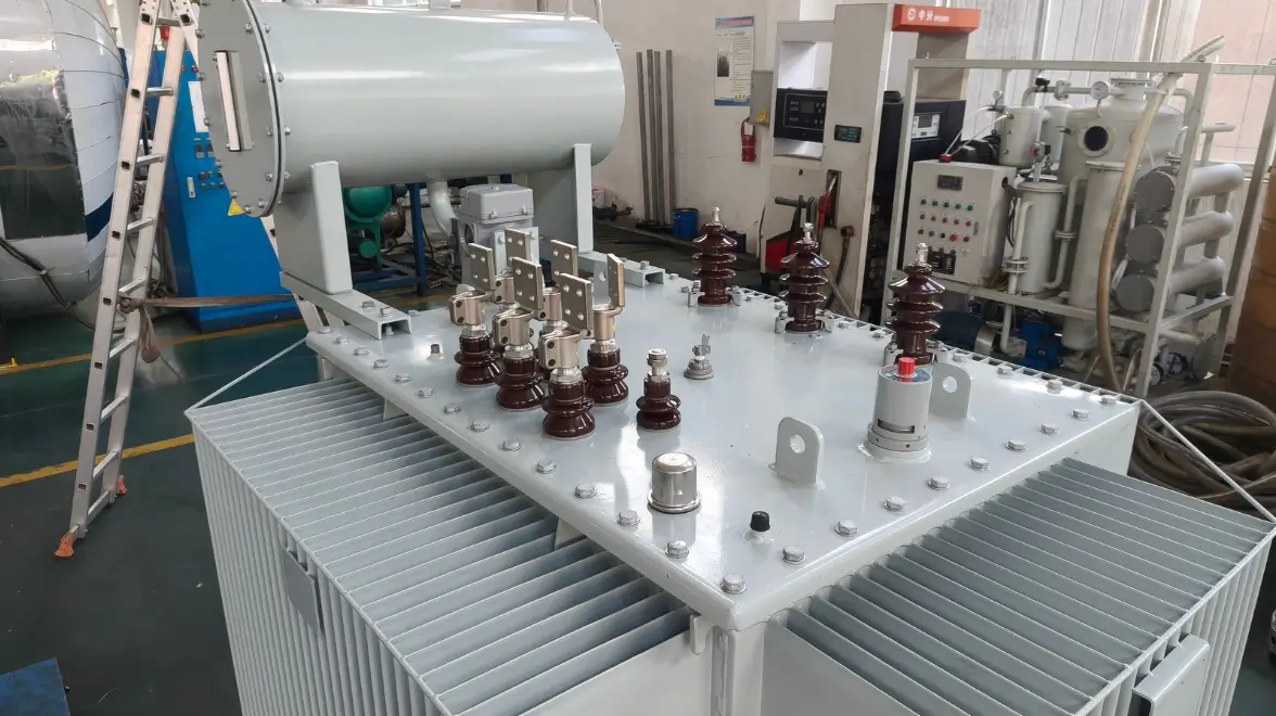
What Is a Transformer Tap Changer?
A transformer tap changer is a device that changes the effective number of turns in one of the transformer windings. Changing the number of turns changes the transformer ratio and therefore adjusts the secondary voltage.
The basic transformer relationship can be expressed as:
V₁ / V₂ ≈ N₁ / N₂
Where:
V₁ is the primary voltage;
V₂ is the secondary voltage;
N₁ is the number of primary winding turns;
N₂ is the number of secondary winding turns.
Tap changers are commonly installed on the high-voltage winding because the current is lower on that side. Lower current can reduce the switching duty and the physical size of the tap-changing equipment. However, the actual winding location depends on the transformer design and system requirements.
Transformer tap changers generally fall into two categories:
- De-energized tap changers, or DETCs
- On-load tap changers, or OLTCs
The critical difference is whether the tap position can be changed while the transformer is energized and supplying load.
What Is a De-Energized Tap Changer?
A de-energized tap changer can only be operated when the transformer is completely de-energized.
It is also commonly called:
- DETC, or de-energized tap changer;
- off-circuit tap changer;
- no-load tap changer;
- off-load tap changer.
These terms are sometimes used interchangeably in the market, but “de-energized tap changer” is the clearest description because it states the essential safety condition: the transformer must not be energized during operation.
Before changing the tap position, operators must isolate the transformer from all possible electrical sources, apply the required lockout and tagout procedures, verify the absence of voltage, and follow the transformer manufacturer’s instructions.
Why Can a DETC Not Be Operated While Energized?
A conventional de-energized tap changer is not designed to make or interrupt load current.
During a tap change, its contacts may temporarily disconnect from one tap before establishing the next connection. If the transformer were energized, this action could produce electrical arcing between the contacts.
Possible consequences include:
- burned or eroded contacts;
- carbonization of insulating material or oil;
- internal short circuits;
- tap-changer failure;
- transformer damage;
- fire or personnel hazards.
For this reason, a DETC must never be operated simply because the transformer appears to be “lightly loaded.” It must be operated only under the de-energized conditions specified by the manufacturer.
Advantages of a De-Energized Tap Changer
A DETC has a relatively simple mechanical and electrical structure.
Its main advantages typically include:
- lower initial cost;
- compact construction;
- fewer moving components;
- low maintenance requirements;
- high mechanical reliability;
- simple manual operation;
- suitability for infrequent voltage adjustments.
A DETC is often appropriate when the supply voltage is relatively stable and the transformer tap position only needs to be selected during installation, commissioning, seasonal maintenance, or a planned shutdown.
Limitations of a De-Energized Tap Changer
The main limitation is that tap adjustment requires the transformer to be taken out of service.
A DETC is therefore less suitable when:
- voltage varies frequently;
- loads change significantly during the day;
- production cannot be interrupted;
- voltage must remain within a narrow operating range;
- remote or automatic regulation is required;
- renewable generation causes frequent voltage fluctuations.
A de-energized tap changer also does not automatically correct voltage changes unless an operator shuts down the transformer and manually selects a different position.
What Is an On-Load Tap Changer?
An on-load tap changer changes the transformer ratio while the transformer remains energized and carries load current.
It is commonly abbreviated as OLTC. In some markets, the term load tap changer, or LTC, is also used.
An OLTC transfers the load current from one winding tap to an adjacent tap without interrupting the supply. This capability makes it suitable for power systems that require frequent, automatic, or remote voltage regulation.
IEC 60214 covers performance requirements and test methods for on-load and de-energized tap changers. According to the IEC application principles, an OLTC is designed to change the transformer ratio while the transformer is energized and loaded without interrupting the supply.
Typical OLTC Applications
On-load tap-changing transformers are commonly used in:
- transmission substations;
- distribution substations;
- power plants;
- steel and metallurgical facilities;
- mines;
- data centers;
- large industrial plants;
- renewable-energy projects;
- critical infrastructure;
- facilities with interruption-sensitive loads.
How Does an On-Load Tap Changer Work?
An OLTC must complete two tasks at the same time:
- Maintain the load-current path during the tap change.
- Prevent an excessive circulating current between adjacent taps.
Adjacent transformer taps have different electrical potentials. Connecting them directly would create a circulating current that could be large enough to damage the winding or switching equipment.
An OLTC therefore uses a controlled transition process.
Make-Before-Break Switching
A typical OLTC establishes a connection to the next tap before fully disconnecting the original tap. This operating principle is commonly described as make before break.
During the short transition period, the OLTC may be connected to two adjacent taps.
An impedance is introduced to limit the circulating current between them. Depending on the OLTC design, this transition impedance may be:
- a transition resistor;
- a transition reactor, sometimes called a preventive autotransformer.
Megger describes the OLTC process as bridging an adjacent tap before breaking the load-carrying tap. A resistive or reactive impedance limits circulating current while the two taps are temporarily connected.
Typical Resistor-Type OLTC Sequence
Although the exact sequence depends on the OLTC design, a simplified resistor-type operation is:
- The transformer carries load through the current tap.
- A transition contact connects the next tap through a transition resistor.
- Both taps are temporarily connected, while the resistor limits circulating current.
- The main current path transfers to the new tap.
- The original tap is disconnected.
- The transition resistor is removed from the circuit.
- The OLTC completes the operation in the new service position.
The transition resistor is used only for a short switching period. It is not intended to remain continuously connected in a normal service position.
Modern OLTCs may use conventional arcing contacts, vacuum interrupters, resistor transitions, reactor transitions, or other manufacturer-specific arrangements.
Main Components of an OLTC
A traditional resistor-type OLTC may include:
Tap Selector
The tap selector identifies the next winding tap. It normally performs the selection function without switching the full load current.
Diverter Switch
The diverter switch transfers the load current from the original tap to the selected tap.
Transition Resistors
The transition resistors limit circulating current while two adjacent taps are temporarily bridged.
Change-Over Selector
A reversing or coarse/fine change-over selector may extend the regulation range without requiring an excessive number of regulating-winding connections.
Motor-Drive Mechanism
The motor-drive mechanism provides the energy and controlled sequence required to complete a tap change.
Depending on the design, the OLTC may also include:
- position indicators;
- mechanical and electrical limit switches;
- operation counters;
- local and remote controls;
- automatic voltage-regulating relays;
- oil-level indicators;
- pressure or gas-actuated protection;
- temperature supervision;
- online condition-monitoring devices.
Not every OLTC contains the same components. Vacuum OLTCs and dry-type OLTCs, for example, may have different switching and insulation arrangements.
How Does Tap Changing Affect Secondary Voltage?
For a transformer with the regulating taps on the high-voltage winding and a relatively constant primary supply:
- Increasing the effective number of high-voltage winding turns increases the ratio and generally lowers the secondary voltage.
- Decreasing the effective number of high-voltage winding turns decreases the ratio and generally raises the secondary voltage.
In simplified terms:
\[ V_2 \approx V_1 \times \frac{N_2}{N_1} \]
If \(V_1\) and \(N_2\) remain constant:
- increasing \(N_1\) reduces \(V_2\);
- decreasing \(N_1\) increases \(V_2\).
However, expressions such as “raise tap,” “lower tap,” “tap up,” and “tap down” are not universally consistent. Their meaning can depend on the manufacturer, utility convention, winding arrangement, control system, or position-numbering method.
Operators should therefore rely on:
- the transformer nameplate;
- the tap-position chart;
- the control schematic;
- the OLTC instruction manual;
- the approved operating procedure.
They should not assume the voltage direction based only on the tap-position number.
DETC vs. OLTC: Main Differences
| Comparison | De-Energized Tap Changer | On-Load Tap Changer |
|---|---|---|
| Transformer condition during operation | Must be de-energized | Energized and carrying load |
| Supply interruption | Required for tap adjustment | Not required solely for a normal tap change |
| Typical operating frequency | Occasional | Frequent or automatic |
| Switching complexity | Relatively simple | More complex |
| Transition impedance | Generally not required | Resistor or reactor, depending on design |
| Control method | Usually manual | Manual, motorized, remote, or automatic |
| Initial cost | Generally lower | Generally higher |
| Equipment size | Usually smaller | Usually larger |
| Maintenance demand | Relatively low | Higher and manufacturer-specific |
| Typical application | Stable voltage and planned shutdowns | Dynamic voltage and continuity-sensitive loads |
The exact cost, size, maintenance interval, and operating capability depend on the transformer rating, voltage class, tap range, switching technology, and manufacturer. A fixed price ratio between DETC and OLTC transformers should not be treated as a universal rule.
Why Choose an On-Load Tap-Changing Transformer?
1. Voltage Regulation Without Routine Shutdown
The principal advantage of an OLTC is that it can adjust the transformer ratio without taking the transformer out of service for each tap operation.
This is valuable where a planned interruption would affect:
- continuous manufacturing;
- critical infrastructure;
- computer and communication systems;
- hospitals;
- railway systems;
- mining operations;
- utility customers.
An OLTC supports supply continuity, but it does not guarantee an electrical system will never experience an outage. Transformer faults, protection operations, upstream failures, maintenance, and other system events can still interrupt power.
2. Improved Voltage Compliance
Voltage varies because of changing load, feeder impedance, power-flow direction, generation output, and upstream network conditions.
An OLTC can help keep the controlled bus voltage within its specified range. Maintaining acceptable voltage supports:
- proper equipment operation;
- power quality;
- motor performance;
- insulation life;
- customer voltage compliance;
- system operating stability.
3. Better Coordination With Reactive-Power Compensation
The reactive-power output of a shunt capacitor is approximately proportional to the square of the operating voltage:
\[ Q \propto V^2 \]
If voltage falls, the capacitor bank produces less reactive power. If voltage rises excessively, the reactive-power output increases and may contribute to overvoltage or overcompensation.
Coordinating OLTC control with capacitor banks, reactors, static VAR compensators, STATCOMs, and inverter-based resources can improve overall voltage and reactive-power management.
The control strategy must be engineered carefully. Poor coordination can cause excessive tap operations, capacitor switching, control hunting, or unfavorable reactive-power flow.
4. Reduced Network Losses in Some Operating Conditions
Keeping system voltage within an appropriate operating band may reduce excessive current and avoid some network losses.
However, it is too broad to state that every OLTC operation automatically minimizes losses. The actual result depends on:
- load characteristics;
- power factor;
- feeder impedance;
- voltage-dependent demand;
- transformer losses;
- reactive-power flow;
- distributed generation;
- control targets.
Modern voltage-control strategies therefore consider more than voltage alone.
5. Remote and Automatic Operation
An OLTC can be controlled by:
- local push buttons;
- a remote control system;
- SCADA;
- an automatic voltage-regulating relay;
- coordinated substation automation.
Automatic regulation allows the control system to compare measured voltage with a target value and issue raise or lower commands after the configured time delay and deadband conditions are satisfied.
The deadband and delay prevent unnecessary operations caused by small or temporary voltage changes.
When Should an OLTC Not Be Operated?
There is no single universal list that applies to every OLTC. Permissible operation depends on its rated through-current, design, protective system, operating manual, transformer condition, and site procedures.
Operators must follow the instructions supplied by the transformer and OLTC manufacturers.
Tap-changing may need to be blocked or suspended in conditions such as the following.
Current Exceeds the Permitted Switching Duty
An OLTC has a rated through-current and specified operating capability. If transformer current exceeds the permitted value for tap-changing, switching may overstress the transition contacts, vacuum interrupters, transition resistors, or other current-carrying components.
Some OLTCs have specified overload capability, while others must be blocked above a configured current threshold. Overload operation should therefore be evaluated against the actual OLTC rating and manufacturer’s manual—not a generic rule.
Abnormal OLTC Protection Alarm
Oil-immersed OLTCs may have dedicated pressure relays, oil-flow relays, gas-actuated devices, or other protective equipment.
An alarm can indicate arcing, gas formation, an oil-system problem, or another abnormal internal condition. Further tap operation should not be attempted until the alarm has been investigated according to the operating instructions.
Protection arrangements differ for conventional oil OLTCs, vacuum OLTCs, gas-insulated units, and dry-type tap changers.
Inadequate Insulating Medium
For an oil-insulated OLTC, operation may be prohibited if:
- the oil level is below the permitted range;
- dielectric strength is unacceptable;
- oil is severely contaminated;
- leakage is detected;
- the oil compartment or pressure system is abnormal.
These conditions do not apply in the same way to every tap-changer technology.
Drive or Position Indication Is Abnormal
Operation should be stopped if the OLTC shows:
- incomplete tap change;
- position disagreement;
- motor-drive failure;
- mechanical jamming;
- unexpected noise;
- repeated protective trips;
- damaged limit switches;
- an operation counter or timing anomaly.
Repeatedly issuing commands to a jammed or incomplete OLTC can worsen the damage.
Maintenance Limit Has Been Reached
An OLTC has specified inspection or maintenance criteria based on factors such as:
- number of operations;
- switched current;
- contact wear;
- oil condition;
- time in service;
- manufacturer recommendations;
- condition-monitoring results.
If a maintenance threshold has been reached, continued operation may not be permitted until the required inspection or service is completed.
Why Can High Current Be Dangerous During a Tap Change?
During a resistor-type OLTC transition, the switching system must carry the transformer load current while also controlling the circulating current between adjacent taps.
The transition components experience combined electrical and thermal stress. If the operating current is above the OLTC’s permissible switching capability, the stress on contacts and transition resistors can rise beyond their design limits.
Possible consequences include:
- excessive contact wear;
- overheating;
- severe arcing;
- transition-resistor damage;
- oil decomposition;
- pressure rise;
- protective operation;
- OLTC or transformer failure.
This is why many transformer-control systems include an overcurrent blocking function for automatic tap-changing commands.
However, the blocking value must be based on the actual OLTC rating, transformer design, relay settings, and manufacturer’s instructions.
How to Select Between DETC and OLTC
A de-energized tap changer may be the better choice when:
- incoming voltage is stable;
- tap adjustment is rarely needed;
- scheduled shutdowns are acceptable;
- simplicity is a priority;
- automatic control is unnecessary;
- lower initial cost is important.
An on-load tap changer may be preferable when:
- voltage changes frequently;
- loads vary significantly;
- supply continuity is important;
- automatic voltage regulation is required;
- remote control is required;
- renewable generation affects voltage;
- the controlled bus must remain within a narrow voltage band.
The decision should consider lifecycle requirements rather than initial transformer price alone.
Important evaluation factors include:
- voltage-regulation range;
- number and size of tap steps;
- maximum through-current;
- frequency of operations;
- load profile;
- short-circuit duty;
- insulation level;
- maintenance resources;
- control and communication requirements;
- required reliability;
- environmental conditions;
- applicable standards.
Frequently Asked Questions
Can a de-energized tap changer be operated when the transformer has no load but is still energized?
Normally, no.
A de-energized tap changer generally requires the transformer to be electrically de-energized, not merely unloaded. An energized transformer can still impose voltage across the tap-changer contacts even if secondary load current is low or absent.
Always follow the manufacturer’s isolation procedure.
Does an OLTC make the transformer uninterruptible?
No.
An OLTC avoids a shutdown solely for normal tap adjustment. It does not protect the system against every transformer, network, protection, or upstream supply failure.
Critical facilities may still require redundant transformers, dual power sources, UPS systems, generators, transfer schemes, or other continuity measures.
Does every OLTC use transition resistors?
No.
Many OLTCs use transition resistors, but others use transition reactors. Modern designs may also use vacuum interrupters and different selector or diverter-switch arrangements.
Is an OLTC always automatic?
No.
An OLTC may be operated manually, electrically from a local control panel, remotely through SCADA, or automatically through a voltage-regulating relay.
Does a higher tap number always raise the secondary voltage?
Not necessarily.
Tap-position numbering and “raise/lower” conventions vary. Operators must check the transformer’s tap chart and control documentation.
Is a DETC more reliable than an OLTC?
A DETC is mechanically simpler and generally requires less maintenance. An OLTC is more complex because it must switch load current without interrupting supply.
However, actual reliability depends on design, application, maintenance, operating duty, installation, and manufacturing quality.
How often should an OLTC be maintained?
There is no universal interval.
Maintenance may depend on elapsed time, operation count, switched-current duty, contact wear, oil condition, diagnostic results, and the manufacturer’s instructions. Vacuum OLTCs may have different maintenance requirements from conventional oil-switching OLTCs.
Conclusion
The difference between a de-energized tap changer and an on-load tap changer is straightforward:
- A DETC changes the transformer ratio only when the transformer is de-energized.
- An OLTC changes the ratio while the transformer is energized and carrying load.
The engineering behind an OLTC is more complex. It must maintain the load-current path while limiting circulating current between adjacent winding taps. This is achieved through a controlled switching sequence using transition resistance or reactance, depending on the design.
DETCs are economical, compact, and suitable for infrequent adjustment. OLTCs are better suited to applications requiring frequent voltage regulation, remote control, automatic operation, or improved continuity during tap changes.
The final choice should be based on the power system, operating requirements, maintenance strategy, applicable standards, and total lifecycle cost.
Table of Contents
- What Is a Transformer Tap Changer?
- What Is a De-Energized Tap Changer?
- Advantages of a De-Energized Tap Changer
- Limitations of a De-Energized Tap Changer
- What Is an On-Load Tap Changer?
- How Does an On-Load Tap Changer Work?
- Main Components of an OLTC
- How Does Tap Changing Affect Secondary Voltage?
- DETC vs. OLTC: Main Differences
- Why Choose an On-Load Tap-Changing Transformer?
- When Should an OLTC Not Be Operated?
- Why Can High Current Be Dangerous During a Tap Change?
- How to Select Between DETC and OLTC
-
Frequently Asked Questions
- Can a de-energized tap changer be operated when the transformer has no load but is still energized?
- Does an OLTC make the transformer uninterruptible?
- Does every OLTC use transition resistors?
- Is an OLTC always automatic?
- Does a higher tap number always raise the secondary voltage?
- Is a DETC more reliable than an OLTC?
- How often should an OLTC be maintained?
- Conclusion